In LTspice, if the timestep is too large, the lowest THD that it will compute with the .four command is limited. So my question is, given a known lowest THD threshold I want detectable for a given frequency, how do I calculate the timestep size and simulation period required? Just using a very small timestep is unacceptable due to the very slow simulation in that case, so I need something close to an exact formula.
Sometimes if you want good results, you have to waithowever long the simulator takes.
Send an email to the guy who is in charge of it. He usually responds within a couple hours. scad3@linear.com
I_F
Send an email to the guy who is in charge of it. He usually responds within a couple hours. scad3@linear.com
I_F
Should be significantly smaller than the period of the highest harmonic you want to analyse. And make it somewhat odd.
I came to use the following, which is also consistent in the parameter naming to jcx's distortion residual "plugin":
.param freq=20Hz
.param period=1/freq ncycles=4
.tran 0 {ncycles*period} 0 {pi/3.14*period/1e4}
This uses approx 1/10,000th of the fundamental period, and with the standard (default) range of 9 harmonics gives an ample x1000 margin. x100 is a good starting point, though (/1e3)
Also sufficient settling time is important, sometimes one needs to sim tens or even hundeds of periods to get stable results. A bonus of more simmed periods is that one can uses more than the last period for the FFT which tends to stabilize the results.
And, of course, turn compression OFF. Choice of solver sometimes make a difference, too, I tend to use the alterate solver.
Best approach is to crank resolution up (iteratevely halving the timestup) until THD doesn't change more than 10% or whatever your uncertainity level is or until sim time skyrockets (tip: sim while you post or lurk around in forums, and use several instances of the programm, so you can work on other things will crunching the numbers). And double check with the sine source to see where your measurent baseline is.
- Klaus
BTW: we had that before, in the SPICE thread and in another recent one. A mod may want move this....
What's that?Originally posted by KSTR
jcx's distortion residual "plugin"
So what's the THD level detectable with that? I'm interested in ranges down to about 0.1 ppm.This uses approx 1/10,000th of the fundamental period, and with the standard (default) range of 9 harmonics gives an ample x1000 margin. x100 is a good starting point, though (/1e3)
Also, I wonder about your timestep size calculation being set independent of the ncycles. I find that either increasing the number of cycles, OR decreasing the timestep, both increase the resolution. It seems that the total number of steps affects the resolution, and thus it is dependent on the number of cycles with some tradeoff.
How is that set? I thought it was set by the start recording time in .tran but you have a 0 for that in the example you gave.Also sufficient settling time is important, sometimes one needs to sim tens or even hundeds of periods to get stable results.
Are you referring to the graphical FFT? I was talking about the logged THD result from .fourA bonus of more simmed periods is that one can uses more than the last period for the FFT which tends to stabilize the results.
I did try that, but I find almost no difference in that result; main differences seem to be length of simulation, and in some circuits one is stable and the other not.Choice of solver sometimes make a difference
That's a good idea; I didn't think of this before...And double check with the sine source to see where your measurent baseline is.
Hi,
>> jcx's distortion residual "plugin"
> What's that?
http://www.diyaudio.com/forums/showthread.php?postid=1333137&highlight=#post1333137
It needs fairly high resolution and settling time otherwise the fundamental will not be nulled out perfectly. Also it is quite CPU-hungry... but the graphical output of the distortion is very valuable at times.
> So what's the THD level detectable with that? I'm interested in ranges down to about 0.1 ppm.
Easily achieved. For example, a diamond buffer design sims at 0.000001% (0.01ppm, -160dB) at 1kHz, 3V, 1k load for example, using 2 periods and a 1/2000th period max. timestep. This is right at the resolution/precision limit of LTSpice (the 6 decimal places in the THD output are there on a purpose), which is about one decade or so lower. Sine generator distortion I could not find any lower than -165dB THD when I tested it, with the individual harmonics no better that -175dB.
You can specifiy the number of periods used, in the .FOUR command, counting backwards from the last period time (base freq specified in the .FOUR). The timestep is an absolute value, thus the number of periods (total time) does not change the result once the circuit has settled after a certain number of periods. That's the tricky part of it, you can only find out by experimentation. Any circuit with time constants from capacitances and/or inductances needs settling time when there is a nonlinearity because this will shift the DC operating point by a minute amount (but maybe enough to change the distortion characteristic). To save disk space one can set the start point of recording for a .TRAN
Since the simulation itself is always to be taken with caution (regarding the underlying model's precision) there is not much point in "tuning" circuits to below 10ppm or so, exept for the fun of it -- which I do have. Nice form of educational computer gaming in a sense, I like to call it "The Quest for the Seven Zeros", game goal is that 0.000000% THD output...
- Klaus
How? A SPICE command reference I'm looking at says that .FOUR uses the last period: "The Fourier analysis is performed over the interval, where TSTOP is the final time specified for the transient analysis, and period is one period of the fundamental frequency. "KSTR said:You can specifiy the number of periods used, in the .FOUR command, counting backwards from the last period time (base freq specified in the .FOUR).
I also have a question about settling time. If the equipment needs settling time when it's first presented with a steady signal, doesn't it also have some settling when presented with non-periodic input, especially large transients in the music? Then really this can affect sound and should be included in the measurement, no?
From LTSpice User Manual (either online help or the pdf):abzug said:A SPICE command reference I'm looking at says that .FOUR uses the last period: "The Fourier analysis is performed over the interval, where TSTOP is the final time specified for the transient analysis, and period is one period of the fundamental frequency. "
"Syntax: .four <frequency> [Nharmonics] [Nperiods] <data trace1> [<data trace2> ...]
Example: .four 1kHz V(out)
This command is performed after a transient analysis. It's supplied in order to be compatible with legacy SPICE simulators. The output from this command is printed in the .log file. Use the menu item "View=>Spice Error Log" to see the output. For most purposes, the FFT capability built into the waveform viewer is more useful.
If the integer Nharmonics is present, then the analysis includes that number of harmonics. The number of harmonics defaults to 9 if not specified.
The Fourier analysis is performed over the period from the final time, Tend, to one period before Tend unless an integer Nperiods is given after Nharmonics. If Nperiods is given as -1, the Fourier analysis is performed over the entire simulation data range."
You've just discovered the reason why circuits behave very different when they process music signal compared to steady state test signals. One very important aspect isn't even modelled in LTSpice , thermal transient conditions (that is, I don't know if/how it can be done in LTSpice. In some professional SPICE versions -- very $$$ software -- transient thermal modelling is usually included, to my knowledge).I also have a question about settling time. If the equipment needs settling time when it's first presented with a steady signal, doesn't it also have some settling when presented with non-periodic input, especially large transients in the music? Then really this can affect sound and should be included in the measurement, no?
Boils down to: even circuits which measure exactly the same with simple continuous test signals may sound different with music. Adequate (whatever that might mean) "music-like" test signals and standardisation of them is still a field of ongoing research...
- Klaus
abzug said:
How? A SPICE command reference I'm looking at says that .FOUR uses the last period: "The Fourier analysis is performed over the interval, where TSTOP is the final time specified for the transient analysis, and period is one period of the fundamental frequency. "
I also have a question about settling time. If the equipment needs settling time when it's first presented with a steady signal, doesn't it also have some settling when presented with non-periodic input, especially large transients in the music? Then really this can affect sound and should be included in the measurement, no?
Besides THD (and other steady-state performance metrics), you will probably also want to try to evaluate the transient response. That is normally defined as the response to a step input. But you can simulate it, for something like an amplifier, with a square wave input, using the "pulse" mode of a voltage source.
Using a square wave input will enable you to check different parts of your circuit for things like overshoot and ringing (and outright oscillation); basically the "cleanness" of the response.
There are standards, for example, for acceptable ringing (e.g. amplitude and number of cycles) at an amplifier's output when it is driving squarewaves into, say, a 2.2 uF capacitive load (although some capacitances _between_ 0 and 2.2uF are often at least as problematical).
The repetition rate (fundamental frequency) of the square wave is not as important as its "edge rates", i.e. the equivalent frequencies for its rise and fall times. (You only need to make the period long-enough to be able to see all of the transient characteristics of interest.)
Note that the maximum slew-rate of a sine wave (in volts per microsecond) = [(2 x Pi) x (freq in Hz) x (amplitude in volts)] / 1,000,000 .
Therefore, for the rise and fall times of squarewaves used for amplifier testing or simulation, for example, IF we assume that we don't need to have slew rates at an amplifier's output that are outside of some "maxfreq" equivalent range, then the maximum slew rate for the input would be 2 x Pi x peak output voltage x maxfreq / gain / 1000000, in V/usec.
That would mean, for example, that for a gain of 20, and a 40v p-p squarewave output, with maxfreq = 22kHz, the input should be a 2v p-p squarewave that would only need rise and fall slew rates of <= 0.138 V/us, i.e. about 14.47 usec risetime and falltime, minimum, giving a maximum slew rate of about 2.764 V/us for a -20v to +20v squarewave transition at the output.
Note that you might also drive yourself crazy, with square-wave transient-response testing and circuit tweaking, if you don't put a reasonable RF (Radio Frequency) lowpass filter at your input.
For power supply simulation, you might want to do an inverse (converse? obverse?) square wave type of test. i.e. Put a current source across the output and have it draw square waves of current. You can also specify a 1-amp AC amplitude in the current source and do an AC Analysis. Then you can have LTspice plot the output voltage divided by the output current, which will give you the output impedance versus frequency.
For actual MUSIC simulation with LTspice, note that LTspice can use standard WAV files, for both inputs and outputs! Using WAV files does seem to make simulations run relatively slowly, though. I downloaded a free demo version of some WAV-editing software called Wavepad (there are many others), so that I could use just short snippets of music, for simulations. Note that, for an amplifier, if the gain were known or measured precisely and was known to not vary over the frequency range used in the input WAV file, then it would be possible to plot, for example, V(OUT)-gain*V(IN), by simply right-clicking on a plot label and entering the appropriate expression, so you could simply SEE the difference between the output and the input.
Other interesting pasttimes include holding down ALT and Left-Clicking on various components, to plot their power dissipation. After a Transient run has finished, you can zoom the plot area to show only the steady-state portion and then hold down CTRL and Left-Click on a plot label, to display the Average and RMS power for the time period in the zoomed (i.e. visible) portion of the plot.
-----
Regarding THD measurements with LTspice:
It looks like Klaus has already given you everything you need. As a relative beginner, just try to remember to always start with some "sanity checks", such as also computing the THD of your "ideal" sine input. If it's not less than .00001, you probably still have compression turned on, in LTspice. You can add ".options plotwinsize=0" on your schematics, so that that can never accidentally happen.
I usually just define a "freq" parameter, with something like ".param freq=20k", and then set the max timestep to {1/(1000*freq)}, initially, and then check to see if the THD changes significantly when I change the max timestep to {1/(2000*freq)}, etc etc. I also use the freq param in my .four statement, e.g. .four {freq} 15 15 V(OUT), to use 15 harmonics and the last 15 cycles of V(OUT).
For the highest accuracy and precision, you will want to try to use the Alternate Solver, since it is about 1000 times more accurate than the Normal Solver, according to Mike Englehardt, the author of LTspice.
By the way: If you are not familiar with the truly-excellent LT-SPICE discussion group, at http://tech.groups.yahoo.com/group/LTspice/ , you will almost-certainly want to go there and register. (Note: Always try to make sure that you search the LTspice documentation, and the group's messages, and the group's Files section, before posting a question.)
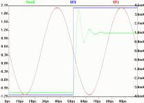
So how do I determine what's reasonable settling time? For example, how much can I test how aperiodicity may affect THD? Here's a simulation result with an actual square wave. I have no idea if this is too long or too slow if say I'm aiming for THD on the order of 1 ppm, and how much a large transient would affect the distortion.
Also, I'd like to ask as well setting up parameters and the FFT options to get the most out of intermodulation sim, say 19 kHz and 20 kHz.
Also, I'd like to ask as well setting up parameters and the FFT options to get the most out of intermodulation sim, say 19 kHz and 20 kHz.
Attachments
http://www.diyaudio.com/forums/showthread.php?postid=1349571#post1349571abzug said:Also, I'd like to ask as well setting up parameters and the FFT options to get the most out of intermodulation sim, say 19 kHz and 20 kHz.
- Status
- This old topic is closed. If you want to reopen this topic, contact a moderator using the "Report Post" button.
- Home
- Design & Build
- Software Tools
- What SPICE timestep for given THD detectability?