Hello all, found this and it seems to fit the bill for a good adjustable test load. I plan on doubling the output section at first and might try it with a couple large surplus transistors like those used in motor drives.
So a couple questions, the 2N6053 are hard to come by after some quick searching. Do I just need to look for a darlington with similar HFE in this case? (matching current and voltage ratings obviously)
Are there any glaring problems with it?
Thanks!
So a couple questions, the 2N6053 are hard to come by after some quick searching. Do I just need to look for a darlington with similar HFE in this case? (matching current and voltage ratings obviously)
Are there any glaring problems with it?
Thanks!
Attachments
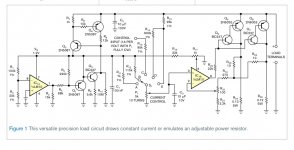
The big feature of that circuit seems to be that the DUT powers it, thus the use of the LM10. It would appear to be unipolar, so it's great for testing power supplies, but not AC devices. If you're willing to include a single 9V battery, you can accomplish the exact same thing with a single op-amp and one or more power MOSFETs, probably with better performance. I put one in a nice box for testing batteries and supplies under an amp, but there's almost no limit on current capacity. Using the MOSFETs keeps the current draw of the circuit near zero, so the battery lasts near to forever. In my case, most of the draw is the large panel meter I used. A high power version will need a huge heat sink, unless you fan cool it, so you might want to power it with a 12V wall wart. Self power doesn't seem to buy much in that case.
Hi Conrad, DC is what I will be testing. I'm looking to scale it up to about 2.4kW of capability. I am looking at some darlington modules that can dissapate about 1.3kW each.
I have the water cooling equip to do that, so it doesn't need to be self powered for fans etc. But, I might make a smaller version that can be air cooled with similar devices like those mentioned in the schem.
So you're saying a regular pass regulator- turned into variable resistor would be simpler. Hmm, that's a good idea.
Ok, here's the circuit published by Siliconix back in Jan '83, in their MOSPOWER Design Catalog. I use a better op-amp, a much lower sense resistor, like .1 ohms, and thus a lower control voltage. This can be regulated with a 431 or zener or whatever. Shouldn't be a problem to parallel more FETs for higher power.
Siliconix Current Sink
Siliconix Current Sink
It's been a few years since I built mine, but I used an AD820 for the op-amp, and a LM385 to give me 2.5V on the adjustment pot. The adjustment voltage will equal the sense voltage so for a 0.1 ohm sense resistor, you get 0.1V/amp. I should probably trace the thing out so I have a schematic. I've never used an IGBT, so somebody else will have to chime in on that one.
edit- digital folks, don't forget you can just use a DAC to control this.
edit- digital folks, don't forget you can just use a DAC to control this.
So, I bought this assembly off fleabay. I couldn't pass it up. I thought it was just a simple variable load or pass bank, but upon closer inspection it seems it is something else. I have attached the schematic I reverse engineered. I'm no ace at eagle so please forgive me.
I originally thought applying control voltage at TP4 varied the base current of the 12 output devices. However when I applied voltage it drew far more current than it should have with a pre-driver and driver. So my guess is a self running regulator once the dc rails are above a certain voltage (I only tested it up to 20v). I may only use it for parts, but it would be nice to know what it is. Thanks!
I originally thought applying control voltage at TP4 varied the base current of the 12 output devices. However when I applied voltage it drew far more current than it should have with a pre-driver and driver. So my guess is a self running regulator once the dc rails are above a certain voltage (I only tested it up to 20v). I may only use it for parts, but it would be nice to know what it is. Thanks!
Attachments
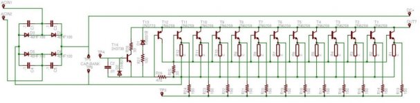
There is always the possibility I drew something wrong, but I'm pretty sure it's true to the p2p wiring. The PNP is pulled down, but it's through the 470ohm resistor. Not sure if a value that low is doing anything. With 20v applied the the output of the bridge, the circuit just sits there. When I put voltage to TP4, I got less than a volt on what I guess is the output. That was with 3A drive current at about 1.5v, the max I of my bench supply. However when I disconnected DC at the bridge, the output voltage stayed there. So what I thnk is the control voltage is appearing at the output, which led me the think maybe the first two stages are for regulation. It seems like the 10W 68v zener does something. Strange one indeed.
So I finally got the circuit Conrad posted built. I'm using a OPA703 and a 2.5v reference for control voltage and it works great.
I'm building two versions. One to do loads up to 600W and one to handle around 2kW. The OPA703 has no problem driving 6 medium power mosfets in the smaller load. However, the large 300A darlington modules I'm using for the big load appear to be a challenge to drive. I burned out two OPA703's while testing them.
Would it be easier to find a beefer single supply opamp or should I build a small current stage to drive the big darlington modules?
Thanks!
Wow, that's a big sink. Not sure how many beefy single supply op-amps there are around, so I'd probably go with some kind of transistor buffer. First, I might stick a small resistor in series and make some measurements across it, to try to find out just what the inputs look like so I'd have a better idea of what to build.
Toasty OPA703's
So, I built a simple buffer in front of the large darlington module. I worked on it until I blew up the rest of my stock of OPA703's. Can you take a look and see if theres a good reason it's blowing opamps like they insulted it's mother? I think I heard ringing, so oscillation is already on the mind. Thanks!
So, I built a simple buffer in front of the large darlington module. I worked on it until I blew up the rest of my stock of OPA703's. Can you take a look and see if theres a good reason it's blowing opamps like they insulted it's mother? I think I heard ringing, so oscillation is already on the mind. Thanks!
Attachments
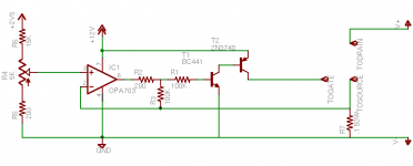
Fast guess is the loop is too slow. I'd try a small cap, say 100pF from pins 2 to 6 on the op-amp, providing some local feedback stabilization. I'm still not sure why the op-amp would fail, though I haven't looked at the data sheet. Check the common mode and voltage limits for the inputs, and install diodes from the feedback input to ground, the supply, or whatever you need to, to prevent exceeding the voltage range of the inputs. You can also add some current limiting resistance to that input. Some op-amps can go to the supply rails regardless, whereas some have surprisingly narrow limits. Usually no problem when the feedback is working, but kaboom if it oscillates or otherwise loses control. 
Good points. I noticed it didn't like it when the source connection was broken while testing with the smaller mosfets. Opamp supply current shot up if the transistor was left connected and the load voltage was removed, thought that was weird too.
I agree the issue is bound to be in the feedback loop. This one can take input V right up to supply rails. The V+ input is ok as the highest it will see is 2.5v, but I haven't monitored the V- in to see if it's being slammed somehow. My other thought is maybe there isn't enough feedback, but thats really just a guess.
I'll order some protection parts with some more 703's. Until then, this project moves to the back of the bench. Thanks!
Checked out the data sheet and it seems like a very well behaved part. If you look at the current vs cm voltage, it shoots up rapidly beyond about 5V. They don't continue the curve, but putting a limit resistor on the input still seems wise. Also, the component values were chosen to drive the gate of a MOSFET, so adding the bipolar stage will require modifying those values to get enough drive- that R1 is probably too high.
Hi Conrad, on the smaller mosfets it was extremely well behaved. R1 was added because the bipolar stage seems to be very sensitive. With the output idling at ~.1v it was slamming the gate of the large module and the PNP was really heating up. I wonder, with such a large R1 would the feedback loop become unstable?
I know what I'm thinking, but doing a really bad job explaining it! It's not really cm that's an issue, so far as toasting op-amps. I've seen many parts, particularly single supply parts, where, if you get too large a *differential* between the inputs, the current consumption goes way up. Some manufacturers mention this, others don't say a word. They assume you're building an amplifier, not a comparator. Unfortunately, if it oscillates differential voltages are to be expected. As for stability, that bipolar stage raises the gain by a lot. Can you do a G=1 follower? BTW, that NPN is dragging lots of current through the PNP gate. You need a limit resistor!!!
- Status
- This old topic is closed. If you want to reopen this topic, contact a moderator using the "Report Post" button.
- Home
- Design & Build
- Parts
- Help with this dynamic test load