No worries Conrad, I really appreciate the help. Brewster is quite a ways from Rochester, but I owe you a beer.
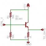
I breadboarded this common collector tonight and drove the big module with it. Worked like a charm. I kinda guesstimated values (not that there are any critical ones here), but if this can be made better please advise. When I get my parts I'll try it once more, with feeling.
I breadboarded this common collector tonight and drove the big module with it. Worked like a charm. I kinda guesstimated values (not that there are any critical ones here), but if this can be made better please advise. When I get my parts I'll try it once more, with feeling.
Attachments
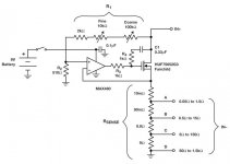
Ok, so I built up the smaller load. After cleaning up wire dress and adding some of the protection measures Conrad suggested, it sort of works. I was getting some nasty ringing on the output of the opamp so I added the 100nF cap between pins 2 and 6 as suggested, I also added a .1uF cap between the gate of the last mosfet and ground. This cleaned up the gate drive quite a bit.
Should the gate drive always look like a sine wave? I ask because I still have this problem-
Around 6v the circuit gets really unstable at low gate drive voltages. Once I have a couple amps of load it's beautiful. Above about 9v and the ringing is so bad at low drive voltage that the current limiting in the power supply I'm using as a Test V source goes crazy and the feedback loop I'm sure does the same and the opamp gets unhappy.
As the Test V is increased the ringing takes longer and longer to subside.
I've attached an album of what the waveform at the gates looks like.
Thanks!
http://s96.photobucket.com/albums/l190/imix500/Small Dyn Load Osc/
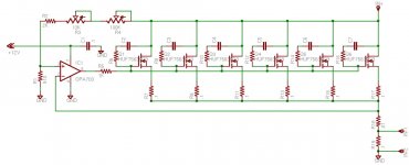
Hi Conrad, it's pretty much still the Siliconix schematic with a .1 sense resistor and a OPA703 driven by a 2.5v reference. It's driving 6 parallel mosfets with a .1 emitter resistor on each.
There are two things I am going to try. One is to add a regulator for the opamp- its powered by a switcher wallwart with a filter cap. The other is to build up another circuit to see if I made a mistake somewhere. I wouldnt really expect this to be really sensitive to layout (its already on a 1" X 1 1/2" pcb) but I'm going to try to clean that up a bit too.
There are two things I am going to try. One is to add a regulator for the opamp- its powered by a switcher wallwart with a filter cap. The other is to build up another circuit to see if I made a mistake somewhere. I wouldnt really expect this to be really sensitive to layout (its already on a 1" X 1 1/2" pcb) but I'm going to try to clean that up a bit too.
FWIW, my experience with CMOS op-amps has sometimes been disappointing, as they have very little drive capability. Even though yours is speced at +/- 10mA, maybe the 703 isn't doing a good job with the MOSFET gate capacitance. Since the gate will always be a few volts above ground, you don't need a single supply op-amp. I'd try plugging in something like an OP-27 or even a 741. Definitely try cleaning up the supply as well.
Back at it again. Resolution for the year is to finish some freakin projects.
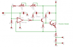
I ended up with this schematic and it works well. Seems to be very stable. The only changes I made was paralleling mosfets and using what I already had, HUF75639G3 and using the OPA703 as the opamp.
I've had three mosfets burn out during testing. They always end up reading between 3-6 ohms both directions. Each mosfet has a .1 ohm emitter resistor and the .33uf/1k combo to help with oscillation. As these are not matched at all, is .1 ohms too low for the emitter resistor? I'm wondering if I'm getting thermal runaway from uneven current sharing.
Thanks!
Attachments
So here's what has changed. I found that the instability of the cmos opamp was from a noisy psu/cooling fan combo. I put a pi filter inline with the fan and stiffened/filtered the supply to the opamp and it's much happier.
The bad news is I just shorted a 300 Amp triple darlington Powerex Module.
Just like the smaller mosfets I was using, it now reads about 6 ohms from E to C.
The module was not running hot and was only dissipating about 400W. It's rated at over 1900W. Am I missing something?
The bad news is I just shorted a 300 Amp triple darlington Powerex Module.
Just like the smaller mosfets I was using, it now reads about 6 ohms from E to C.
The module was not running hot and was only dissipating about 400W. It's rated at over 1900W. Am I missing something?
Attachments
- Status
- This old topic is closed. If you want to reopen this topic, contact a moderator using the "Report Post" button.
- Home
- Design & Build
- Parts
- Help with this dynamic test load