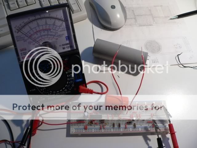
The topic of testing power supply filter caps seems popular, and many people don't have a capacitance meter or bridge. There also seems to be some fear or reluctance to build such a thing, so I wanted to see how easily it could be done using essentially sweepings from the top of my workbench. No board, no box, just the simplest bridge that would measure large value filter caps for both value and dissipation factor. Turns out it's really easy, though hopefully anybody doing this won't have exposed line voltage like the fool that threw this one together. I had hoped the bridge could be nulled with headphones, but the signals are quite small, and either a scope, or maybe an audio amp and speaker, are needed. Or a meter with a sensitive AC scale. Just adjust the two pots until there's no signal and measure the values. The more ambitious might make a calibrated dial.
In this case, I'm checking a 47000uF cap, and my Rn was 5200 ohms. The Rt was 101.8 ohms. Tossed into the formulas on the attached schematic, that gives 52000uF and D=0.38, a perfectly good cap.
Schematic
An externally hosted image should be here but it was not working when we last tested it.
In this case, I'm checking a 47000uF cap, and my Rn was 5200 ohms. The Rt was 101.8 ohms. Tossed into the formulas on the attached schematic, that gives 52000uF and D=0.38, a perfectly good cap.
Schematic
Hi Conrad, that looks great!
I believe I have an AC meter that could be used, would the measuring points for finding null from adjusting the two pots Rn and Rt be at DUT1 and DUT2? Would you then read the value of each from the pots themselves?
Also I’m not exactly sure what the ‘D’ of D= 0.38 is?
At what point would the cap be discharged??
Thank you for posting this - Stan
Hi Stan, "DUT" stands for "Device Under Test", a common industry acronym. You hook your cap to DUT1 and DUT2. The scope or meter connects to ground at the bottom and the top of the bridge. This is a nice arrangement with the detector grounded, since you can use just about anything, including just pumping the signal through an audio amp and speaker.
Dissipation factor is a figure of merit- low is generally good. It's actually the ESR, but with frequency included in the equation.
Don't feel you have to use the values I did. Just work the formulas backwards for the caps you want to test, and pick whatever is close and happens to be lying on the workbench. None of my other bridges will test a 50000uF cap, so these values made sense. If you want to test smaller caps, say under 5000, it's best to make Ra larger. A real bridge would have a range switch so Ra could be 1, 10, 100, etc. That way the dial calibration stays the same- if one bothers to make a dial")
edit- Since this is an ac test, discharge the cap before the test. It won't have much voltage on it after the test, so you don't have to do anything when done.
Dissipation factor is a figure of merit- low is generally good. It's actually the ESR, but with frequency included in the equation.
Don't feel you have to use the values I did. Just work the formulas backwards for the caps you want to test, and pick whatever is close and happens to be lying on the workbench. None of my other bridges will test a 50000uF cap, so these values made sense. If you want to test smaller caps, say under 5000, it's best to make Ra larger. A real bridge would have a range switch so Ra could be 1, 10, 100, etc. That way the dial calibration stays the same- if one bothers to make a dial
edit- Since this is an ac test, discharge the cap before the test. It won't have much voltage on it after the test, so you don't have to do anything when done.
Come on, tell us the formula to swap between DF and ESR with frequency. Or is Rt=ESR?Conrad Hoffman said:Dissipation factor is a figure of merit- low is generally good. It's actually the ESR, but with frequency included in the equation.
Does the distortion in the test signal affect the accuracy of the result?
Andrew is just teasing- one can tell because it takes a smart fellow to ask the distortion question! Now, math is my absolute worst subject, but this is manageable by anybody. Remember that omega is just 2*pi*f, or 377 for 60 hz (314 for 50 hz). The dissipation factor, DF, is omega*Rt*Ct. It's also omega*Rx*Cx, because the C and R on the left bottom of the bridge are scaled to the C and R on the left top of the bridge, by the ratio of the resistors on the right side of the bridge. So, first you balance the bridge for zero signal, and find the mystery capacitance: Cx=(Rn/Ra)*Ct. Hopefully you picked a nice close tolerance film cap for Ct, as the result will only be as good as that cap. Now you find the DF using omega*Ct*Rt. The DF of the bottom pair is the same as the DF of the top pair, but Rt does not equal Rx. The impedance of Cx is very small as the value is far larger than the reference cap Ct, so the resistance needed to give the same DF will be much lower. Thank goodness, because it means we can use a sensible value of pot instead of having to look for a 2 ohm pot! Since we know DF and Cx, it's just a matter of rearranging the formulas to find Rx, which is the ESR for our mystery cap: Rx=DF/(omega*Cx) Remember that ESR is only valid for one frequency, so be careful with Spice simulations.
As for distortion, the bridge will only null at a single frequency, and even that requires a perfect capacitor with a linear loss element. So, if the waveform is distorted, the null won't be as deep and clean. OTOH, for measuring filter caps it's no big deal. If you built a precision standards bridge working at part-per-million resolution, it would matter a great deal. Something I find more interesting is that the perfection of the null says something about the linearity of the capacitor. If you raise Ra and compare small value caps like a film vs. a high capacitance ceramic, you'll find a perfect null can't be achieved with the ceramic because it's non-linear with voltage. If you can't achieve a perfect null with the film, it's usually because the dissipation pot has a step off zero. the first time I built the bridge, my (too large) pot wouldn't go below a couple hundred ohms, and I couldn't balance it. The large value wasn't really necessary, since I reject capacitors with high dissipation factor, so I went to 1k.
Hopefully I've gotten all that right...
You're quite welcome- hopefully somebody will actually scrounge through their junk bin and build one. I don't find many bridge fanatics to talk to.
Now, if we make this too complicated one might be better off to just go find a used GR 1650. They used to sell for between $75 and $150, but I haven't checked lately. Still, the other thing people here want to measure is inductors. All you have to do is move the Ct and Rt pair over to the right, and put the Rn over on the left. Now you have a parallel inductance bridge. Connect your inductor to the DUT terminals and balance as before. Lx=Rn*Ra*Ct, though you'll have to work the math backwards to find out what the best Ra is to put you in the right range. Hint- range switch with a set of resistors! The Q of the inductor is 1/(omega*Ct*Rt).
That's the easy swap. You can get series inductance directly, but it's easier to just convert if you need it. I posted a nice conversion program long ago- here it is again.
Couple more things- The DF of a capacitor tends to stay about the same over a wide frequency range. Thus, when somebody tells you the DF, you can make a quick quality determination for the cap, if the number is valid where you want to use it. If they just tell you the ESR, that's far less useful, unless they also give you the exact frequency of measurement. General users of capacitors should think in terms of DF. Switching power supply designers typically go with ESR, since they tend to work at a specific frequency.
I tried to build a bridge to measure caps for a passive crossover in my latest speaker project.
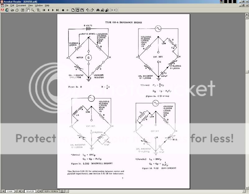
I couldn't get it to work. I used a drawing from a GR650 manual as guidance.
I used fixed resistors and my signal source was the output from my sound card that I varied trying to get a null. I could never find a null.
I wish I could get it to work. It would be a lot cheaper than buying a meter and more in the spirit of DIY.
Satterfi, keep trying! You notice that most bridges won't test huge caps. I don't remember the upper limit on the 650, though I have two of 'em. So, if you duplicate the 650 circuit, it probably won't null. What you have to do is use the fairly simple equations and rearrange them to give you the part values that will null for the size cap you want to test. Somewhere I have a spreadsheet for that if you want. Or, start with the values I showed in the first post. The cap has such a low impedance that the signal will be small- you'll have to null with a scope. I don't know if it can be done with headphones at low frequencies. The 650 used a meter or headphones, but the usual frequency was 1000 Hz- easy to hear, but too high for testing big caps. Your sound card also may not have enough power to really drive the thing. That's why I used a little filament transformer- lots of current. I still added a series resistor to limit the current, since all that's across the transformer is the big cap and a 1 ohm resistor, pretty much a short circuit. Go back to my first circuit, give it a shot, and let me know what you find.
Satterfi, I just noticed that you were using fixed resistors and varying the frequency, am I right? That's a quick road to frustration, as the null will be sharp and narrow. The value of the cap is also unknown, so finding the null might be hit or miss. You really need a pair of pots with knobs to hit this correctly. Once you have that, put a dial on the pots and mark the scale based on the resistance of the pots using the formulas.
an analogue voltmeter is ideal.satterfi said:I don't have a scope so my biggest challenge might be detecting the null.
The more sensitive the scale the better, but it will need an adjustable attenuator (variable resistor) in series to prevent the needle going off the scale, until you can get your fingers used to adjusting the null without overshooting in the opposite direction.
Since the classic "meter" for a bridge is a tuned null detector like the GR 1232-A, and that's nothing more than a high gain amplifier and narrow band filter...
take that nice protoboard and stick in whatever low grade op-amp you didn't want to use for an audio project, like a 741, and a couple resistors, and put some gain before your meter. If you want to be really fancy, make it a bandpass filter at 60Hz. You'll have no trouble seeing the null that way! BTW, a meter with a needle is far superior to a digital meter for this purpose.
An interesting thing about bridge circuits is that at balance the output voltage is zero. That means that whatever meter or amplifier is attached, doesn't have any current flowing through it. It could look like ten ohms, but since the voltage is zero, no current flows (at balance only). Thus, you can use an inverting amplifier with a low value input resistor, and get tremendous gain without having to worry about circuit loading. Just stay within the legal limits for input voltage if the bridge is supplied with more voltage than the op-amp.
Yes, IMO everyone with analog intentions should read everything Jim Williams has ever written and buy his books as well! Though most of what he has presented doesn't cover new ground, I found his discussions of probes and bypass caps extremely valuable, not to mention the little circuits like the ultra-fast risetime generator and the bypass cap test method. The bridge article covers a lot of ground, including some active bridge arrangements not often seen.
I was in NYC yesterday and hit the window just right. Up here in Rochester we had an inch and a half of snow in an hour this morning, with more coming down, then a big storm predicted for Sundayish. I put a big load of wood next to the wood stove this morning
I was in NYC yesterday and hit the window just right. Up here in Rochester we had an inch and a half of snow in an hour this morning, with more coming down, then a big storm predicted for Sundayish. I put a big load of wood next to the wood stove this morning
Conrad Hoffman said:I was in NYC yesterday and hit the window just right. Up here in Rochester we had an inch and a half of snow in an hour this morning, with more coming down, then a big storm predicted for Sundayish. I put a big load of wood next to the wood stove this morning
William's book "Analog Circuit Design" is a gem -- containing as it does chapters written by Pease, Philbrick etc.
We are laying in an extra supply of Jack Daniels.
Ok, I finally got ambitious enough to put this in a box. If you use a 10Kohm ten turn pot with a turns counting dial, it will read out in capacitance directly. The ten turn pots are quite good at high frequencies, 500kHz at least, though this bridge is mainly for 50/60 Hz use. Though my goal was a bridge just for high value electrolytics, I tossed in a range switch so it's now a general purpose bridge. The only pot I had for the DF dial was a very non-linear A-B carbon comp, I actually measured the resistance vs rotation and marked the dial to match. Thus the slightly weird spacing. Though the meter isn't shown (an HP3400 on the 3mV scale), the bridge is shown measuring an old 51000uF Powerlytic. It measured almost exactly 51000uF with a DF of about 0.4- a perfectly good cap. The input voltage from a filament transformer and a 40ohm limit resistor was about 1.5VAC. Note the nice heavy leads and lugs to the cap. You're balancing the cap against a one ohm resistor, so the connections should be low resistance. Why build that complicated digital stuff, when a couple resistors will do the job? 
Schematic is here.
An externally hosted image should be here but it was not working when we last tested it.
Schematic is here.
That looks excellent.
Can an oscillator can be the voltage source instead ?
I'll build this this week.
(this this )
)
I have an LCR meter (ESI 410, 1 MHz)...but I haven't a clue on how to use it. I have never seen a manual for sale anywhere, or it's sister the 295 (?). I don't even know what the "1 MHz" is referring to.
btw, fyi (OT)....
http://www.jptronics.org/radios/GR/GR_History.pdf
I love the old equipment. Eventually I'll get around to learning what this real Potentiometer I have does....
http://i5.photobucket.com/albums/y177/Midiot/DSCN2619.jpg
I don't think this would ever be a DIY project....
http://i5.photobucket.com/albums/y177/Midiot/DSCN2612.jpg
http://i5.photobucket.com/albums/y177/Midiot/DSCN2616.jpg
=RR=
Can an oscillator can be the voltage source instead ?
I'll build this this week.
(this this
)I have an LCR meter (ESI 410, 1 MHz)...but I haven't a clue on how to use it. I have never seen a manual for sale anywhere, or it's sister the 295 (?). I don't even know what the "1 MHz" is referring to.
btw, fyi (OT)....
http://www.jptronics.org/radios/GR/GR_History.pdf
I love the old equipment. Eventually I'll get around to learning what this real Potentiometer I have does....
http://i5.photobucket.com/albums/y177/Midiot/DSCN2619.jpg
I don't think this would ever be a DIY project....
http://i5.photobucket.com/albums/y177/Midiot/DSCN2612.jpg
http://i5.photobucket.com/albums/y177/Midiot/DSCN2616.jpg
=RR=
You can only use an oscillator like the old GR ones that had transformer output. The input to the bridge really needs to float, and that's why the filament transformer works well. You should also limit the current with a 40-100 ohm resistor, since the cap and other side of the bridge are very low resistance at the test frequency.
Nice potentiometer- Guildline is excellent (and expensive) stuff. Without looking in detail, it looks like it's basically a 6-digit voltmeter. The voltage reference would have been a Weston standard cell (mercury/cadmium) at 1.018 or so volts. If you haven't already, go research "Kelvin Varley Dividers" as a first step to understanding the thing ;-)
Nice potentiometer- Guildline is excellent (and expensive) stuff. Without looking in detail, it looks like it's basically a 6-digit voltmeter. The voltage reference would have been a Weston standard cell (mercury/cadmium) at 1.018 or so volts. If you haven't already, go research "Kelvin Varley Dividers" as a first step to understanding the thing ;-)
- Status
- This old topic is closed. If you want to reopen this topic, contact a moderator using the "Report Post" button.
- Home
- Design & Build
- Parts
- Testing PS filter caps