I saw some neat meters that can be put on the amplifier faceplate.
Can something like this be done on my amp?, how does it hook up? from the speaker output? I am a novice with amp32 pictured here.
I recall even seeing a amplifier case with auto amp meter on it...
gychang
Can something like this be done on my amp?, how does it hook up? from the speaker output? I am a novice with amp32 pictured here.
An externally hosted image should be here but it was not working when we last tested it.
I recall even seeing a amplifier case with auto amp meter on it...
gychang
Attachments
Basically, these meters are µAmp-meters or milli Amp-meters.
the auto amp-meter u have seen is basically the same but the current measument is done using a small value shunt R.
U cannot use these meters directly in an amp. They will need the additional drive circuitry.
Google for VU meter and then search within results for analog.
Some drive circuits will be available on the datasheet of LM3915, but u will need some basic understanding to use them for the analog meter.
Gajanan Phadte
I know you can use this amp meter using an resistor in parallel with it, but can't precise how many ohms do you need.
No, not for vu meter purposes. This is the method of indicating high current.
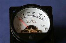
If u look closely on the meter dial, there will be some writings and symbols, which indicates movement type and parameters.
Gajanan Phadte
This article might be of some help with the VU meter circuit.
http://www.jlmaudio.com/AT51 DIY VU.pdf
http://www.jlmaudio.com/AT51 DIY VU.pdf
if you look carefully at the face of the meter in his pix, you will see the orange coil below the scale, so it is definitely a moving-coil type. you will need to run your amp through a voltage divider, a rectifier/filter, and an adjustable current shunt. i don't know how many mA full scale your meter is, or how much output power your amp has, so i'll use an example.
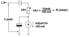
for a 50 watt amp, assume about 45V peak. from your pix, the "face value" of the meter is 100mA full scale. we want DC feeding the meter. so first let's get the 45V peak value down to a useable level, or about 4.5V. we'll need a max of 100mA when all is said and done so our voltage divider should provide this.
so the voltage drop needed before the metering circuit is about 40V (it's actually 40.5, but 40 is close enough). 40V/200mA (the meter will be one one of 2 branches of this voltage divider.) gives 200 ohms for the "high side" resistor. 4.5V/100mA gives 45 ohms (this is the first branch of the divider). the other branch of the divider feeds a bridge rectifier with a 100uf electrolytic and a 100ohm pot across the DC output. this then connects to the meter. the pot is connected with the wiper and one end tied, so that this becomes a variable 2 terminal resistor.
the pot is adjusted for the meter showing full scale with the mp driven just to clipping
Howzit Nordick,
xxx uA is the fsd (full scale deflection) that simply means it will be full scale if xxx uA flows through it. Then use it as an ammeter with series resistance, in other words you convert the ammeter to reading volts.
Measure the meter dc resistance then add a series trim pot that is in the calculated range and trim it until full scale is reached with the applied voltage.
The reading will be porportional to the voltgae developed across the speaker. The capacitor would cause it to be average measuring.

- Status
- This old topic is closed. If you want to reopen this topic, contact a moderator using the "Report Post" button.
- Home
- Design & Build
- Parts
- meter on the DIY amplifier faceplate?