Hi folks,
I have a gorgeous CM Labs 35D in for repair.
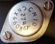
The transistors are all made by RCA, but are house marked for CM labs and their numbers are of course, like CM1 - CM12 and obvious stupidity like that.
Pic attached of output transistor.
I've done the usual site search and crossref, ST, NTE, blah, blah...
Anybody have an idear?
Thanks!
I have a gorgeous CM Labs 35D in for repair.
The transistors are all made by RCA, but are house marked for CM labs and their numbers are of course, like CM1 - CM12 and obvious stupidity like that.
Pic attached of output transistor.
I've done the usual site search and crossref, ST, NTE, blah, blah...
Anybody have an idear?
Thanks!
Attachments
Hi Peter,
Don't know if you got this reply on the Bozak forum, but now that I see the pic, the CM 10 on the multi component board in the front is a high voltage medium power germanium transistor (at least Vce 120v), which you will probably not find today. But a silicon pnp sub will do - the only thing is that the bias current will not be right if you replace it with a silicon device and you would have to make up the difference of about 0.3 volts in the bias circuit.
Before we get into any modifications, how do you know that it is at fault? Have you measured whether it is open or shorted? Simple test - take a non-digital ohmmeter on the lowest scale, and with the pins facing you vertically place one of the leads on the base (lower one) and the other to either the other pin (emitter) or to the case (collector). Repeat the readings with the leads on the meter reversed. There should be a big difference on the readings with the meter leads one way vs the reading the reversed way. If so, the transistor is probably still good.
Just finished repair of a 35D for Ed Coleman. But I just sent it back today. If I had it opened up, I could tell you what you could use. In any case, before you are done, you should replace all the small electrolytics, because as they get leaky and old, they don't function as they should, and some of the original MEC black plastics with epoxy ends were not very good to begin with, as we found out later. The Seimens were a lot better. And the input caps should be replaced with lower leakage tantalums.
If the relay doesn't click in, the relay coil may be burnt up from the two 3.3K 2w resistors underneath that usually gives a burned area on the board below. This is because at about 3 watts into the carbon resistors, they generally overheat and with a negative coefficient resistance past a certain temperature, they even reduce in value tending to overheat the coil, burning it up.
Also, it could be one or more of the outputs could be shorted, which prevents it from powering it up. Simple check with an ohmmeter to see if emitter to collector are low ohms, and that each output transistor is okay by checking diode polarity from base to emitter and base to collector for each, as before with the CM10. Connector is provided at each output transistor to help with this simple test. If all is good there, then it should power up at least 80 volts or so, so then the relay should kick in.
If it still stays pretty low, there is a short somewhere. Or maybe the big 250 ohm, 20w resistor gave up. Before you even apply power again, check whether the relay coil is still alive. If so I would immediately remove the two carbon 3.3k 2 watt resistors (if you measure less than 1.5k, it's in trouble). Sub with a single 1.8k, 5 watt cement wire wound from Mouser or Digikey. If the coil is dead, you will want to get another 24 v relay with approx 600 ohm coil. I assume you want to keep the protection circuit alive and functioning.
Get back to me to see what you have found. I can try to talk you through the rest of it, when I know more.
Wayne Chou
Hi Wayne,
I'm Gregg, fixing this for Peter
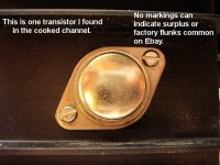
I'm interested because I found this (see pic) in there too, which has already been replaced and may have caused the trouble in the first place.
I haven't had time to poke around much more or test each part individually.
Thanks for stopping by, it's greatly appreciated!
I'm Gregg, fixing this for Peter
I'm interested because I found this (see pic) in there too, which has already been replaced and may have caused the trouble in the first place.
I haven't had time to poke around much more or test each part individually.
Thanks for stopping by, it's greatly appreciated!
Attachments
Hi Gregg,
Don't recognize this one - on the heat sink, right? Subs for anything on the heat sink one could use 2N3773's. But if they have been cooked, it might have affected the drivers before them, as well as the transistor on the same heat sink.
I would do the simple ohmmeter test, as stated previously, on the driver transistors as well, and compare from one channel to the other, before unsoldering everything, even if they are being loaded by other circuit elements. If they don't compare favorably, then unsolder them to check more thoroughly.
Note previous post and check relay, replace two watt resistors underneath, and all small electrolytics, as well as tantalums for input.
Keep me posted,
Wayne
Don't know if you got the other message.
In the beginning I thought it looked like the TO-3 on the circuit board. But now that I see it is the output transistor on the heat sink. Scratch the comments about the PNP germanium (CM11), though we might have to address that issue if it had been damaged.
Wayne Chou
In the beginning I thought it looked like the TO-3 on the circuit board. But now that I see it is the output transistor on the heat sink. Scratch the comments about the PNP germanium (CM11), though we might have to address that issue if it had been damaged.
Wayne Chou
Hi Wayne,
Thanks for the info!
Got time to look at this today and am a little confused...
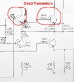
Q18 is toast. Open on every pin (that's the no-name sub). Q19 is OK, BUT it tests as a PNP than an NPN the schematic shows
Now going to poke around the driver board...
** edit **
Q16 toast. B-E shorted, B-C is a thermistor.
Cheers!
Thanks for the info!
Got time to look at this today and am a little confused...
Q18 is toast. Open on every pin (that's the no-name sub). Q19 is OK, BUT it tests as a PNP than an NPN the schematic shows
Now going to poke around the driver board...
** edit **
Q16 toast. B-E shorted, B-C is a thermistor.
Cheers!
Oh okay,
The CM 10 is an output transistor on the heat sink, and a good equivalent is a 2N3773. I think in those days, we pulled special voltages from the line before it became the 2N3773. The other driver is on the board, and I don't recall if it is a TO-66 package. If so, I was just recommending a more robust sub to someone else - a 2N4233 which has higher breakdown voltages, and better speed. It wasn't available in those days.
I don't think you would have to go back further than that as far as the damage is concerned. Try that and I think you should be up and running, but don't forget the cap and resistor upgrades. Bias at the positive end of the output cap should be about 47 volts or so - adjusting for symmetrical clipping. Compare with the good side. Keep me posted.
Again,
While you're ordering parts, please do those upgrades as well, on the main board and the input - the caps affect gain, distortion, hum and noise and pops when they get old. Some get leaky, others just don't filter well. And I found that the black plastic ones, with the epoxy ends particularly have a short life span compared to the others. On the board underneath, the caps control the soft start and the protection. And the two 3.3k, 2 watt resistors should be removed (they probably have singed the board already) and will burn out the coil of the relay (better check that) because they tend to NTC when they get hot, which makes it a run away condition. I would replace them with a SINGLE 1.8k, 5 watt square cement type and spaced off, like the others on the board.
Wayne
Hi,
Yup, I sure will do the upgrades. I keep a suitable stock of quality caps on hand for new designs that I can use in this too. I use 1.8K/5W in one preamp design, so that's easily enough done too
What about those howitzer shell sized electrolytics, are they prone to failure?
Cheers!
Yup, I sure will do the upgrades. I keep a suitable stock of quality caps on hand for new designs that I can use in this too. I use 1.8K/5W in one preamp design, so that's easily enough done too
What about those howitzer shell sized electrolytics, are they prone to failure?
Cheers!
Actually, they are pretty good - nice description though - they could do some damage, if overvoltaged. Once had one go through the roof like a rocket trying to stress one out. Lot of energy stored there. Being computer grade, they tend to last a long time, but as you know, we aren't as resilient as we were once anymore.
But if you have a scope handy, looking at the ripple on the power caps will tell you a lot about how good they are, when you are pulling power into the load.
Wayne
But if you have a scope handy, looking at the ripple on the power caps will tell you a lot about how good they are, when you are pulling power into the load.
Wayne
PS>
I guess my edit didn't come through. Here's a link http://store.americanmicrosemiconductor.com/2n4233.html?gclid=COym35_0gY8CFRa_WAodrCxY3w. where you can buy a minimum of 3 for under $30 US. Unfortunately, I think the power supply is at 80 volts (check that, because I don't remember), so there are very few choices in the TO-66 package, which seemed short lived to me. The TO-220 is a later device, and more choices are available. And although it won't look the same, if forced to go to another device, I can't see why a later device with higher voltage capacity wouldn't work.
Wayne
Hi Wayne,
Fortunately, I found the transistors in Vancouver at a fraction of the cost of that website.
Bad thing is, I found three more dead ones, two TO-5 cased CM12 (Q13 and Q15) and the CM11 (Q17). I hadn't tested farther back than the driver's, so I didn't catch Q13 and Q15 before. Q17 must have been killed when I powered up (Q16, 18 and 19 survived).
The CM9/2N4233 crossed to a NTE175, which has a complament to NTE38, so I assume I can use a NTE38 for the CM11. I just need a replacement number for CM12 if possible
The relay circuit works flawless again. All polarized caps (other than power and output) have been replaced and the audio input caps changed to polypropylene.
I can go to Vancouver again Tuesday.
Cheers!
PS: Zener diode CR6 I should replace too, but it's listed as a 1N1974, which does not exist and 1N974 is too high of voltage for C25 (1uF, 10V).... what is that one?
Perhaps you should post a schematic to me. I searched my archives and cannot find the schematic which has all the Q numbers. So I want to be on the same page with you. The CM11 is a PNP germanium, and a TO -3, so it is not exactly a complement of the CM 9 which is a TO-66. If you sub the CM11, which I know you can't get germaniums anymore, you will have to increase the bias resistor from the base of the pre-driver CM 12 to the base of CM 13, now 680 ohms, to make up the 0.3v difference. Theres about 4 ma flowing through that, so if you do that, 750 ohm would do just about right. All these devices need to have a Vceo of about 100v.
The one zener I recollect is near the beginning of the chain - 6.8 v from the CM 12 emitter to anode ground. No particular tolerance - the pot on the board will center the swing no matter if it is not perfect. Gladly, CM12 can be readily sub'd with any NPN wide band device that can stand the voltage. They are generally small signal, with no particular power requirement, but should stand at least 1/4 watt. However, I don't see how the damage got back that far unless the pre-driver CM12 shorted out to begin with, along with the CM9 driver. And that's almost going all the way back to the beginning. But post the schematic so I can be sure we are talking the same language.
Wayne

Q14, a CM13, was OK. It's a germanium too? (the Vb-e seems to show that anyway)
Would not changing R46 overbias it?
Cheers!
** edit **
NTE127 - TO3 cased, HV PNP Germanium!
http://www.nteinc.com/specs/100to199/pdf/nte127.pdf
More:
http://www.nteinc.com/Web_pgs/Germanium.html
Would not changing R46 overbias it?
Cheers!
** edit **
NTE127 - TO3 cased, HV PNP Germanium!
http://www.nteinc.com/specs/100to199/pdf/nte127.pdf
More:
http://www.nteinc.com/Web_pgs/Germanium.html
That's more like it - had to clean it up a little bit in Photoshop, and sharpen it up, but now I see where you are.
Good pick - the NTE 127. I had forgotten that was most of the application for a PNP Ge power - in the horizontal output. But I don't recollect if the CM13 was also a Ge, but if you read about 0.3 Veb, then it probably is.
Probably obvious to you, but have you tried disconnecting power to the entire bad side, and measuring test points on the good side - if there is a good side? Also, when I had a bad amp in for repair, I usually plugged it into a Variac and came up slowly - without a load, and see if the power supply comes up proportionately. If there was a shorted transistor you wouldn't come up very far on the voltage. And if all was okay, the relay would kick in at some point. With limited voltage, you can also measure some points that make sense or not, and see some conditions of over current, before everything gets destroyed all over again. If you don't have a Variac or equivalent, maybe plugging in the amp in series with a low wattage lamp, with increasing changes of lamp wattages to bring up the voltage on the amp in small steps.
As far as the diode is concerned, don't remember if this was a factory thing or not - on both sides? You can probably tell from the soldering whether that was original or not.
Changing that 680 ohm to 750 was only a suggestion if you had to replace the Ge TO-3 with something in silicon - it would have to compensate the biasing for the additional 0.3v Vbe drop to 0.6v. But since you found a Ge replacement, you wouldn't have change it.
This one is a tough one - never had one that wiped out so many. Usually an ouput and a driver before it, at worst. Doing a great job - will try to continue with the help. We'll get it to work.
Wayne
- Status
- This old topic is closed. If you want to reopen this topic, contact a moderator using the "Report Post" button.
- Home
- Design & Build
- Parts
- Transistor sub help needed