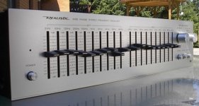
I got this for nothing. It's a Realistic model #31-2000 made in Korea for Tandy.
It's in fine shape, no scratches or damage. It works fine, seems to have good functional control over the frequency bands.
Is it a good unit? I know, most "audiophiles" would say these are nothing more than distortion mills, no place for even the best of them in a superior system.
I like the ability to contour the sound to my preference and at least try to overcome some of the room problems. I also like the way this unit looks - it matches the equipment that I have.
OK, main question: If this is truly a pile of garbage circuit wise, is it worth building a circuit of filters for it with low noise op-amps?
The current circuit is all discrete, using (mostly) transistors 2SC1222 and 2SA953.
A pic of the insides is coming but here's the front:
Attachments
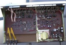
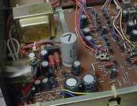
Looks like a sensible layout but does look like a cheap board and components. (the single turn trimmer resistors in the middle of the left hand board)
Plenty of potential improvements, power supply filtering, any electrolytic series capacitors, replacing ribbon cable with screened cable.
Give the pots a clean and see if you like it. It may be a distortion mill but so is a SET tube amp!
Who cares what anyone else thinks?
Plenty of potential improvements, power supply filtering, any electrolytic series capacitors, replacing ribbon cable with screened cable.
Give the pots a clean and see if you like it. It may be a distortion mill but so is a SET tube amp!
Who cares what anyone else thinks?
Hey Mike,
It seems to work well as is, but I'm up for improving it. Good points with the caps, filtering and ribbon cable.
It's my intention to integrate it into my active 3-way system (whenever that gets done ). My HTR does have pre-outs but no power-ins (or a tape loop), so I really haven't been able to give it a try with good speakers.
I though someone on here would be familiar with this unit and lend some guidance as to it merits.
It seems to work well as is, but I'm up for improving it. Good points with the caps, filtering and ribbon cable.
It's my intention to integrate it into my active 3-way system (whenever that gets done
). My HTR does have pre-outs but no power-ins (or a tape loop), so I really haven't been able to give it a try with good speakers.I though someone on here would be familiar with this unit and lend some guidance as to it merits.
Certainly if anyone has seen one, it would be you.
Like I said, I haven't had the opportunity to give it a serious listen. I expect it will reveal it's deficiencies on my new speakers.
If the unit were only used for "cut" and not "boost" do you think this could make a difference. If I rebuilt the circuit, I would have it so it would only cut the selected frequency, with no option for boost.
It also has overall gain, controllable with a pair of front panel knobs. It also has a bypass button for quick A/B comparison.
Limhes said:lots of phase shifts throughout the whole frequency band.
This unit uses inductors so phase shift is certain. If I were to re-build, I would use phase coherent filters, without using inductors.
I'm still waiting on the opportunity to give it a good listen. My ears ain't what they used to be, so it might fool me.
I dig up this older thread because I have made some tests on this equalizer.
First was a listening test. I found that if I used it to cut only, it worked very well. The sliders cover quite a sweep, too much in my opinion - they go from -12db to +12db. Cutting (or boosting!!)any part of the audio spectrum by any more than 2-3db means there are other, more serious problems to address.
I had the unit attached between my pre-out on my Yamaha HT receiver and the input to my (new) active amp . It was fine, I could effectively reduce some of the frequencies that I find too harsh on most speakers (low mid to mid - 300hz to 1000hz).
I then ran some tests on Right Mark Audio Analyzer. Connected through my lab computers sound card, I ran three tests: 1/ with the unit on but all of the sliders flat. 2/ All of the sliders on both channels with a 2db cut. 3/ All of the sliders on both channels with a 2db boost.
Here's a screen shot of the results window. First test of the group is the sound card test (provides the baseline performance).
Attachments
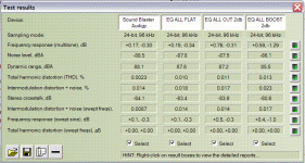
As it can be seen, the equalizer adds about .0077% THD with all of the sliders at 0db. Cutting by 2db worsens the distortion by only another .0001%, and a 2db boost will increase THD by .0002%. This is not too bad, if you are starting out with a low THD amp to begin with.
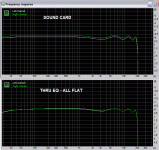
That's THD. What do the frequency responses look like?
Here's the first two: the sound cards natural frequency response and beneath that, the equalizer a 0db boost/cut.
That's THD. What do the frequency responses look like?
Here's the first two: the sound cards natural frequency response and beneath that, the equalizer a 0db boost/cut.
Attachments
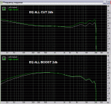
And this is the frequency response of the last 2 tests, cut 2db and boost 2db.
It's not very linear. More boost or cut in the mid bands with the same slider travel. BUT, no big drops or peaks, so not that bad.
My conclusion is that I'll use this equalizer and be satisfied with it's very good performance...for now
It's not very linear. More boost or cut in the mid bands with the same slider travel. BUT, no big drops or peaks, so not that bad.
My conclusion is that I'll use this equalizer and be satisfied with it's very good performance...for now
Attachments
Re phase shifts
Hi,
A filter with a cap alter phase shift as frequency change..... as well as a filter with an inductor....... as well as a gyrator (usually as inverted cap filter > inductor), useful in order to make a more ideal inductor. An uneven frequency response from a speaker also means phase shifts. If an EQ is set flat there should be no phase shifts regardless if gyrators or inductors are used.
If one uses an equaliser to smooth speaker response (if succeeded), phase performance should improve. Problem is that with a graphic EQ, Q and centre freq seldom corresponds with the needed correction points of a speaker. And as usual, more electronics in the audio path should be weighted against the response improvement.
Re: Re phase shifts
Hi 4fun,
That's very true, a parametric eq would be better. If I need to cut only 3 or 4 bands to get the sound I like, maybe I should build one. In the meantime, I'm happy with this one.
A few more components in the signal path doesn't trouble me, as long as they are not degrading performance.
I'm thinking about making a few improvements to this one. Just to see if it's performance would increase measurably.
4fun said:
Problem is that with a graphic EQ, Q and centre freq seldom corresponds with the needed correction points of a speaker. And as usual, more electronics in the audio path should be weighted against the response improvement.
Hi 4fun,
That's very true, a parametric eq would be better. If I need to cut only 3 or 4 bands to get the sound I like, maybe I should build one. In the meantime, I'm happy with this one.
A few more components in the signal path doesn't trouble me, as long as they are not degrading performance.
I'm thinking about making a few improvements to this one. Just to see if it's performance would increase measurably.
DJ Exprice said:SEXY DESIGN
Why, thank you!
defect9 said:I got one of those. A/B comparison between bypassed and all faders to 0 is intriguing in how much the sound is affected (possibly due to age, for all I know). As a budget eq for processing though, not bad. The upgrades should help at least a little
Mine sounds different too (not worse, just different). Even with the sliders set to 0, the signal is still going through the filters. This is why I was pleasantly surprised when I looked at the frequency response and it's nearly identical to the sound cards response. There's a slight drop near the bottom (see post #11 pic).
I'm going to upgrade the power supply first, with new smoothing caps and twice the capacitance. If that makes an improvement, I'll do more.
Re: Re: Re phase shifts
Hi John,
If you don't plan to keep it in original shape for any original restore plans there is quite easy to alter centre frequencies and Q values to ones desire. You could even make one or two sections parametric.
This site has some info, sparse of math but maybe interesting:
http://www.geofex.com/Article_Folders/EQs/paramet.htm
MJL21193 said:
Hi 4fun,
That's very true, a parametric eq would be better. If I need to cut only 3 or 4 bands to get the sound I like, maybe I should build one. In the meantime, I'm happy with this one.
A few more components in the signal path doesn't trouble me, as long as they are not degrading performance.
I'm thinking about making a few improvements to this one. Just to see if it's performance would increase measurably.
Hi John,
If you don't plan to keep it in original shape for any original restore plans there is quite easy to alter centre frequencies and Q values to ones desire. You could even make one or two sections parametric.
This site has some info, sparse of math but maybe interesting:
http://www.geofex.com/Article_Folders/EQs/paramet.htm
Re: Re: Re: Re phase shifts
Thanks for that, a lot of useful info there. I'll be taking a closer look.
I got ambitious last night and did some power supply work on it.
This unit has a small transformer, maybe 25VA, with two secondary windings. The first winding provides for the op amp supply (+/-15V), the second is for the discrete section of the board, and provides +56V.
They have a 330uF/80V Elna for smoothing on this supply and have split it from there to two rails (I assume one for left, one for right). These rails are decoupled with a pair of 220uF/63V caps.
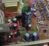
I changed the 330uf for a 6800uf/100V and the 2 220uf I changed for 2 new Panasonic 220uf/100V.
I then did the sliders flat test with RMAA. There was a slight improvement in THD, but hardly enough to justify the changes. I removed the 6800uf and put in a new Elna 330uf/100v.
Pic shows the original. The three caps are visible in the centre and near the bottom.
4fun said:
This site has some info, sparse of math but maybe interesting:
http://www.geofex.com/Article_Folders/EQs/paramet.htm
Thanks for that, a lot of useful info there. I'll be taking a closer look.
I got ambitious last night and did some power supply work on it.
This unit has a small transformer, maybe 25VA, with two secondary windings. The first winding provides for the op amp supply (+/-15V), the second is for the discrete section of the board, and provides +56V.
They have a 330uF/80V Elna for smoothing on this supply and have split it from there to two rails (I assume one for left, one for right). These rails are decoupled with a pair of 220uF/63V caps.
I changed the 330uf for a 6800uf/100V and the 2 220uf I changed for 2 new Panasonic 220uf/100V.
I then did the sliders flat test with RMAA. There was a slight improvement in THD, but hardly enough to justify the changes. I removed the 6800uf and put in a new Elna 330uf/100v.
Pic shows the original. The three caps are visible in the centre and near the bottom.
Attachments
Changing the smoothing cap from 330uF to 6800uF was good for a .0005% decrease in THD, with no other visible performance increase on the tests. No, I didn't take it and listen to the results. I wouldn't hear a difference anyway (I think it sounds fine as is).
Part of the reason for this exercise is to prove to myself how much of a difference these "tweaks" make. You read a lot here about how different power supply caps sound this way or that way. I've always believed that to be nonsense.
Here it is with the caps changed, with the large 6800uF sitting in a chair that's too small for him. As I mentioned above, I changed that for a new 330uF and left the 220uFs alone.
Attachments
- Status
- This old topic is closed. If you want to reopen this topic, contact a moderator using the "Report Post" button.
- Home
- Design & Build
- Parts
- Comments, opinions on this equalizer.