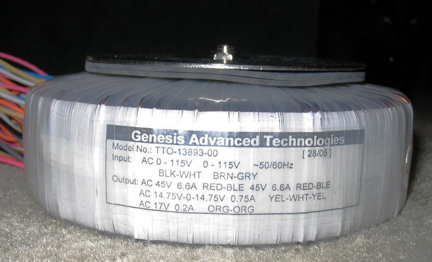
Hey I never thought I would be asking this, but I'm a bit confused. I have a Toroidal transformer built either for or by Genesis Advanced Technologies (The speaker company) and its rated at 90vct, however the wires are listed as Red-Blue 45vac Red Blue 45Vac. I assume if I tie two together and leave two apart, say tie the blues together, and leave the reds apart, that will give me the 45V-0-45V CT setup I want, with the Blue-0 and the reds equaling 45vac. Is this correct.
 do not short circuit threads of same coil-winding !
well if I understand you right, you don't believe that the same colors are the same thing? I guess I'm not really sure what comes off the end of those leads, but I would have thought connection Blue and Blue and Red and REd would give me 90 volts AC, and connecting it the way I said would give me 45-0-45. Now Can't I bypass your light idea by simply measuring the voltage? Again though, its AC so I'm not really sure why I would read 0 volts, I expect to still see 45.
An externally hosted image should be here but it was not working when we last tested it.
Also datasheet say to connect same colours for Vs-0-Vs
It is enough to measure the tension.
with light bulb it can try also power output.
Just a note then, when I got it, the wires were all connected to a Molex connector, with the Reds and Blues connected together. So there was one pin with two reds going into it, and one pin with two blues going into it. This again makes me think that the (0) is going to be either the red or Blue together, and then the 45V's will either be the Red or Blue.
Excuse my ignorance if this is completely off, but given that this is AC coming out, shouldn't it be the same. I mean, its essentially the same as balanced power correct, and with those, either leg to ground gives you half the nominal voltage. So if you have a 120 volt, as in the US, Balanced power system, it would be 60-0-60, with the 0 being at ground. The + and - would flip flop constantly, at 60hz in the US, between those two legs. Other than phase, which way I have it shouldn't matter I wouldn't think. I figure I have to run a (0) and (45) into a rectifier for each leg seperate, and then have DC 45-0 and 45-0. Then I tie the two 0's together to get my CT 45-0-45.
I just looked at the PCB I have for my rectifier board, I had an extra from my chip amp project. They just want AC1-AC1 and AC2-AC2. I believe the correct way to hook this up will be AC1(Red)-AC1(Blue) and AC2(red)-AC2(blue). I wouldn't say I have an advanced understanding of electronics, but this seems pretty basic, and unless I'm missing something, I don't understand why that won't work.
Thank you, I looked up Plitron's drawing as well, which is the same as yours, and started to better understand what you were saying. Plitrons had the voltages in, and they did have the V1 and 02, if you will, connected, not the 0 and 0, and then leave the V's open. I still don't fully understand why it matters, but I will test before I start hooking things up.
An externally hosted image should be here but it was not working when we last tested it.
In the transformer the tensions are relative.
as 0V is assumed the thread connected to mass.
in AC mains The neutral is the thred that have a null or little voltage
respect to the earth.
In AC voltage there are not the poles + - but the phases.
In a series circuit if the phases are concordant the tension it is added
if the phase are discordant the tension is subtracted.
Black point on Your schematics indicate the phase of winding.
Bye
(Italy Time 00:03 )
)
as 0V is assumed the thread connected to mass.
in AC mains The neutral is the thred that have a null or little voltage
respect to the earth.
In AC voltage there are not the poles + - but the phases.
In a series circuit if the phases are concordant the tension it is added
if the phase are discordant the tension is subtracted.
Black point on Your schematics indicate the phase of winding.
Bye
(Italy Time 00:03
)Yes I just went and tested out the various connections and was able to figure things out. Thank you for your help though, it was very useful. The transformer actually had the Red and Blue taps in pairs, so it was easy to see which red and blue went together, and which didn't. That way I didn't accidentally connect the coils together. Testing it with the Red from one coil to the Blue of another gave me the expected 45 volts, actually 48 volts at no load, and 96 when connected together and measuring from the other red and blue, as you have in your diagram. I tried what I was thinking, connecting the blues together and measuring the red's of each side, and I got almost the same reading, a slightly lower voltage of 46. I assume this is because one is in phase and the other out, and its canceling a little of the wave's amplitude? I'm just guessing not really sure. Anyway, I now feel comfortable moving onto the next step.
- Status
- This old topic is closed. If you want to reopen this topic, contact a moderator using the "Report Post" button.
- Home
- Design & Build
- Parts
- Connecting toroidal transformer