3 inches of any conductor when grounded to a lump of metal (such as a chassis) will have a quarter-wave resonance somewhere around 950MHz. The exact figure would depend on any dielectric loading from the shrink-wrap, and the Litz insulation, which would tend to reduce the frequency. Let's say 900MHz. Isn't that near a cell phone band?
In what way could this influence the sound if that were the case?
DF96
Might I ask you to investigate true, individually insulated strand, Type 2 Litz wire? I have been told by an RF engineer that the individual rope lay twists and insulated strands of wire in those lay ups, constitute antenna shadowing and that the noted proximity rejection of this cable type arises from that.
Certainly there is no audible "radio source" style noise injection, regardless of how many speaker, amplifier, preamplifier and CD player loops are added to a system. On the other hand I have no idea what cell phone injected signal might sound like in an audio system, and I have a booster tower just one block from my home. That information might be useful, if it is going to be an audible effect. Unfortunately my oscilloscope is aimed at measuring the transformers I design and is old tech as far as frequency capability goes. Any light you can shed here would be helpful.
Bud
RFI is believed to make things sound worse. Seems pretty clear that's not what's really happening as it doesn't sound worse, and often sounds better.
Thought so. We must have bad taste then.

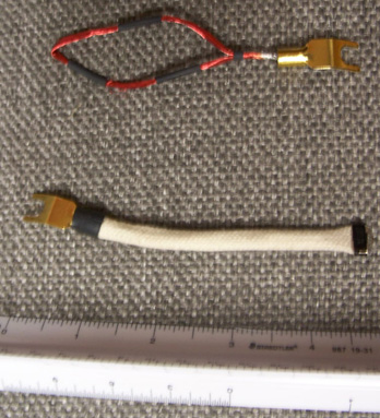
Thanks for sharing the photo. I had seen it before and realized that I put the shrink wrap on the entire loop, not just on one side of the loop.
OK, so I thought what difference can it make ?? I pulled the 3 pieces of shrink wrap off and put it on each side of the loop as in the pic, and really expected no difference..
Oh my gosh!! Very noticible difference and for the better. It changed the sound stage. I had had an exagerated sense of depth prior to the change. Its still 3d but not now more forward and where it should be. Very natural. I believe it cleared up a little problem I was having with an overly pronounced upper frequency response.
The architecture of these things count. I use about a 4" 100x loop of 34 guage mgnet wire. On the neg of the speakers and on the star ground inside my DAC. Its a 6n2p tube output and the ground is on the plate power filter near the tubes and the RCA output.
very nice.. thanks Bud
Obviously the idea is that they may actually reduce the amount of RF noise affecting the audio circuit.RFI is believed to make things sound worse. Seems pretty clear that's not what's really happening as it doesn't sound worse, and often sounds better.
How? there may be many ways.
The loop(s) may work as notch filter(s) on the line(s) where they are attached to, effectively "absorbing" (filtering) RF noise.
Or perhaps the loop(s) "inject" some picked-up RF noise on one "side" of the circuit (ground) balancing out the RF noise picked up by another "side" of the circuit, thus effectively cancelling (part of) the noise from the circuit operation.
Anyway (if there really is any real, sensible effect from this tweak), the "RFI tuning" effect seems to be the only reasonable explanation proposed so far (sorry Bud, but the "electron pool" idea is just plain pseudoscience nonsense).
As suggested, the tweak "optimization" instructions does indeed sound a lot like the act of empirically tuning RF resonance(s) and Q factor.
Or perhaps the loop(s) "inject" some picked-up RF noise on one "side" of the circuit (ground) balancing out the RF noise picked up by another "side" of the circuit, thus effectively cancelling (part of) the noise from the circuit operation.
It works like pine needles do to RF. the tuning frequency of the antenna is shunt to ground and thus, attenuating the surrounding radiated area by that frequency. Upper and lower harmonics are attenuated in porportion but more elememts grounded in the array increase bandwidth response of the RF radiation attenuator.
I have some incredibly thin litz. I think each strand is 52 gauge, and I believe there are 32 of them. All in silk I believe (could be cotton).
How thick a bundle should this be? Should the completed gauge of 18 awg? From the photos, all insulation should be removed correct?
This is a very interesting looking tweak. I shall try it.
How thick a bundle should this be? Should the completed gauge of 18 awg? From the photos, all insulation should be removed correct?
This is a very interesting looking tweak. I shall try it.
I took them off my amp and speakers the other night and a warmth that had disappeared returned to the sound. The jury is out on these. It might be I do not have the right configuration.
Or, it might be because of the hour of the day I am listening. There are so many variables involved.
This sounds like the perfect thread for me to get involved in. Call it SY bait, if you will. I will lie on the Groundside Electrons Train tracks and make SY attraction noises. It should work.
I'm late to the party, but I'll race to the end ...and hopefully similar as been said already.
My two cents:
In all, though, to be serious..a good solid ground return path is necessary. Anywhere in a given circuit where there is any withdraw or transposition of current from the system occurs, is where a good ground return should be located. It should be symmetrical and similar to the current use and exit from that given transposition circuit/point. The sum total capacity of the combined grounds should be the same as the current draw from the wall..and should be arranged to have a simple path and treated as carefully as any delicate signal, with regard to coupling, position and dynamic needs.
Think of the entire ground path as passing the signal. For in essence, it is.
Imagine an audio cable made up of the exact construction of the ground path in the given gear. For in essence, that is exactly what you have.
Last edited:
It works like pine needles do to RF. the tuning frequency of the antenna is shunt to ground and thus, attenuating the surrounding radiated area by that frequency. Upper and lower harmonics are attenuated in porportion but more elememts grounded in the array increase bandwidth response of the RF radiation attenuator.
This is an incredibly interesting idea, can we pursue it please? How does an event like this work out when buried in a field event of fair strength, i.e. the connection point of a speaker system or the back panel of a CD player? Certainly a piece of type 2 Litz requires a saturated field event before it picks up anything at all.
KBK, my point exactly! Unfortunately this sort of care is not common. SY has been baited by the way. He has a few sets of the commercial Ground Control in various stages of completion. Thinks they are worthless too. But gives me points for sincerity....
Bud
This sounds interesting Bud, what did I miss.
Sounds like you guys need to look up Eric Dolan. One of the recent experts on ground wave RF 'punching'. (longitudinal wave launch via inductive groundplane punching). The massive inductive dump punches the groundplane and creates a huge longitudinal 'elastic dish' effect and thus the differential results in a longitudinal wave which creates a high amplitude 'normal' wave.
Good ole' inductance. Not anything like the textbooks tell you it is. Textbooks are notes for engineers.. and have nothing (who are only allowed to calculate, never postulate or think on theory) to do with the reality of what inductance actually is. Go back to the original theory and explorations... and you'll get the facts of the origins of 'LCR' which tell a whole different story.
Last edited:
You didn't miss a thing. That was a description of what a loop of Litz wire resembles, to an EMF. I just wanted to pursue the idea.
As for LCR, well, I design and build audio transformers that have built in passive demagnetization and no hysteresis storage loses, utilize coupling surfaces and dielectric materials in the coil to create an electrostatic circuit and use that circuit to reinforce and focus the antenna event, coupling across the dielectric barriers. I have been to the theories found the first order derivations from them wanting, for anything but low frequency power transform and have wandered off on my own. Ground control, absolutely stable, neutral, unshielded, ultra low loss cables and a process for causing drivers in speakers to actually perform as they theoretically should, have been the result of the wanderings..... and did you mean Eric Dollard?
As for LCR, well, I design and build audio transformers that have built in passive demagnetization and no hysteresis storage loses, utilize coupling surfaces and dielectric materials in the coil to create an electrostatic circuit and use that circuit to reinforce and focus the antenna event, coupling across the dielectric barriers. I have been to the theories found the first order derivations from them wanting, for anything but low frequency power transform and have wandered off on my own. Ground control, absolutely stable, neutral, unshielded, ultra low loss cables and a process for causing drivers in speakers to actually perform as they theoretically should, have been the result of the wanderings..... and did you mean Eric Dollard?
BudP,
Has Walker Audio paid you for your idea? I just saw they offer for sale: 'Eliminator Directional Antennae'. To quote them (actually an article from The Absolute Sound) "The Eliminator is a pair of high-speed directional antennae made of pure silver wire with pure silver spades at one end of each wire. The wire has been tested for directionality and treated cryogenically with a deep immersion process. By attaching the spade ends to the negative binding posts of an amplifier, users will hear a difference in as little as 30 minutes and will have 90% break-in in 20 hours."
I hope I'm not riling up anything here as I've seen you devices for sale commercially but credit was given to you by that particular vendor, but I didn't see your name metion in the article. To be fair though I have not looked on Walker's sight.
GC Quandries
I first installed 26-inch zip wire loops to negative speaker terminals and I became a believer. Immediately, I thought I heard something different. After listening a while, I sensed there was a deepening in the perceived breadth and width of the sound stage. Vocalist seemed to be well defined in location in a 3D sense.
Based on material I had on hand, I subsequently made a pair of GC loops from (8) 6-inch long loops of 30-guage RS magnet wire. I twisted the strands together, used flux and dipped each end of the loops into a solder pot. I installed the 1/2-inch pieces of shrink wrap appropriately split as prescribed by BudP. I replaced the zip loops with these mag wire loops. Initially, the new
mag wire loops were a little bright, but after a about 8-hours of break in I did not detect a major difference in the sound between the two loop topologies.
I used 8 loops of the 30-gauge because that cross sectional area was around 18-gauge. I computed this based on the area of BudP's topology. I have since reread what I could find in this thread and others trying to determine if I should use smaller gauge with more strands.
Considering the skin effect involved should topologies made up of smaller gauge with more strands be considered over larger gauge and fewer strands?
Others have made up loops comprised of large number of strands. Is the number of strands more important than cross sectional area?
I plan to make some loops out Teflon clad Cat5 wire. I will be using the cross sectional computations as to the number strands.
As for the Walker items, if you want to deliberately insert RF signals into your chassis circulating currents and spend money doing it, buy from them.
The Ground Controls use type 2 Litz and the rejection of external EMF fields is extremely efficient. That you can achieve the same audible results when changing from an obvious antenna, the loop of zip cord, to a loop made from wires with as high a proximity rejection of EMF as type 2 Litz, as used in Ground Control, does call Walker's "claims" for operating mechanism into question.
Of course, if you cannot hear a difference with any of the wire loops, wires to special rare earth's in a puck, 8 foot long metal ribbons, stub antennas or Ground Control, then all of the verbiage on this thread are called into question and the Walker claims are even more irrelevant.
Bud
- Status
- This old topic is closed. If you want to reopen this topic, contact a moderator using the "Report Post" button.
- Home
- Design & Build
- Parts
- Groundside Electrons