Ed LaFontaine said:@lf,
Your pictures are worth thousands.
Thanks for the time you have spent.
")
Add my vote too!! Great JOB!!!


You all do know
You all do know that some guy is going to build some of these things and sell them to the general audio public for 500 dollars a pop. I hate what has happened to my audio sport in the last 30 years in the USA. No schematics, no real information from manufactures just mumbo jumbo jargon.
It used to be that you couldn't sell audio equipment without a schematic... no one would buy it.
Geezz if I were going to spend kilobucks on an amp I would at least like to know what the hexx I.m buying.
End of todays rant...
@lf said:Hi!
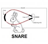
Please use this picture for all corrections if something is wrong/missing.
Be vewy, vewy qwiet - I'm hunting wabbits!
Attachments
@lf,
Your pictures show the correct use of the loops, as I understand it. Everyone should experiment with alternate usage and materials.
For the placement of the shrink wrap tube I usualy move the end pieces back from the wire ends. I do not imagine that it makes any difference with the results.
Bud
Your pictures show the correct use of the loops, as I understand it. Everyone should experiment with alternate usage and materials.
For the placement of the shrink wrap tube I usualy move the end pieces back from the wire ends. I do not imagine that it makes any difference with the results.
Bud
I'd like to add my thanks to @lf.
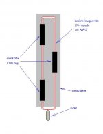
But, I didn't picture it quite the way you did. From bud's picture in post#40, it showed a length of litz wire exactly
as in your first diagram, (here's where we differ), Instead of forming it into an open loop, as you did, and Simon did in
his picture, I thought Bud folded it tightly in half. Then instead of placing the shrink wrap as you have shown, he used
the three pieces (one at each end , and one in the middle ) to bind the folded wire together, then slid it into a cotton
shoelace. His picture only shows the tinned wire protruding from one end of the cotton lace.
I'll be very interested to hear Buds' thoughts. Perhaps they're both right.
My placement of the plastic , when the wire loop is to be put into a cotton sleeve, is as you describe, but I do not put the plastic tube around both wires.
If you imagine a loop of wire that is squeezed down to two parallel portions, one portion has two pieces of plastic, with a space left between them just big enough that the third piece of plastic, on the other leg, will fit into that gap. This is only done to make the package look less lumpy. It is not important to the sonic event.... or, at least I don't think it is important.
Thanks for the drawings @lf, they will help many silent investigators of this foolish but interesting event actually try it out. And thanks to Phil for providing a quick and easy way to make a good enough wire bundle..
Bud
@lf,
Alex from Oz has worked out a spread sheet for just that activity. He started a thread here.
http://www.diyaudio.com/forums/showthread.php?postid=1720882#post1720882
So, assuming you have Excel, with a bit of reading you should be set to try it with a reversible activity. He does recommend tape, because it is a much less subtle improvement than the paint method I have used for 35 years. He also has a method for dealing with Bass ports that seems to work very well.
Bud
Back at the beginning of this lengthening thread c2cthomas provided this article.
http://www.analog.com/UploadedFiles...20828AN_345.pdf
However, the link no longer works. If you will PM me I will send you a copy, assuming I can unearth it. It turns out I do have the document.
Bud
http://www.analog.com/UploadedFiles...20828AN_345.pdf
However, the link no longer works. If you will PM me I will send you a copy, assuming I can unearth it. It turns out I do have the document.
Bud
Thanks Bud, I think I found it in my pile of files. I'll have a closer look.BudP said:Back at the beginning of this lengthening thread c2cthomas provided this article.
http://www.analog.com/UploadedFiles...20828AN_345.pdf
However, the link no longer works. If you will PM me I will send you a copy, assuming I can unearth it. It turns out I do have the document.
Bud
http://www.analog.com/static/import...14948960492698455131755584673020828AN_345.pdf
There is a whole load of reference material regarding grounding schemes for electronics. It is tied in with signal integraty and EMC.
You will notice in the abocve example taht hanging wires on digital grounds increases the noise and is to be avoided.
The return signal (which is realy what is being discussed, ground is a misnomer) and how it behaves is frequency dependant. It allways follows the path of least Impedance, this being resistive for low frequency, inductive for high frequency and capacitive for RF frequencys.
Analog audio comes into the low frequency and thus resistve path of least inductance. What works for one type of circuit will often not work for another.
Digital consists of square waves which are loaded with harmonics, but the event that cauases all the problems is when the signal changes, it is the rise time and resultant differential wave travelling over the PCB that causes all the grief to designers. Hence PCB's are designed with contigous ground planes and often more than on to allow for tight coupling between the signal and its return path, (the ground consisting of strips mentioned earlier would not work very well with high rise time signals).
I would like someone to explain how adding the tails to a USB port would improve the sound, USB data transmission is not the same as CD signals where the 16 bit data is burried in the Reed-Solomon error correction, and due to the bit rate, is prone to errors. Data transmitted over a USB interface is 100% correct when it reaches the recieving end, (bit errors etc are corrected by resending packets) thus what is being corrected by adding the tail and how can it effect sound that is going to be DA converted furthe down the chain!
I would like to see as I said earlier reseach into the origional use of these pig tails, speaker terminals etc, where as well as analogue signals there is also inductive elements, ie the drivers motor.
- Status
- This old topic is closed. If you want to reopen this topic, contact a moderator using the "Report Post" button.
- Home
- Design & Build
- Parts
- Groundside Electrons