Hi,
the light bulb provides an automatic limiter if there is a wiring fault.
Once the equipment is up near full voltage and proved to be correctly wired, the tester bulb & it's plug top/socket is removed. It should be re-inserted each time you modify part of the equipment.
You could fit a bypass switch but this should more safely be a hold to make type rather than a flip over (latching) in case one were to forget to reset the bypass to off ready for next test.
The bulb works in opposite fashion to a thermistor.
At low currents it provides little resistance and let's most of the voltage through, but if the current is high enough to warm the filament the bulb starts to limit and becomes even warmer starting to glow or in worst case becomes bright indicating a fault when it absorbs almost all the mains voltage.
Do not try to set bias in an amplifier with the bulb in-line. The low voltage after the bulb will upset the amp and all the setting you are trying to achieve.
ps.
the fixed resistor referred to in post 3 will burn out if the transformer were wired out of phase and would be at mains voltage creating an additonal danger.
Rather like a poor-man's variac.
Some info here:-
http://www.vintage-radio.com/projects/lamp-limiter.html
Some info here:-
http://www.vintage-radio.com/projects/lamp-limiter.html
Oops!
I seriously misread the original poster's question. I use 10 ohm resistors in series with the supply to the output transistors (in place of the onboard fuses). Bias starts off at minimum, and is slowly increased until the Vdrop reflects to the required quiescent current. Of course, if the resistors start to smoke, then there's a fault somewhere....
I seriously misread the original poster's question. I use 10 ohm resistors in series with the supply to the output transistors (in place of the onboard fuses). Bias starts off at minimum, and is slowly increased until the Vdrop reflects to the required quiescent current. Of course, if the resistors start to smoke, then there's a fault somewhere....
AndrewT said:
Do not try to set bias in an amplifier with the bulb in-line. The low voltage after the bulb will upset the amp and all the setting you are trying to achieve.
Missed this before, and it may be part of my problem....Can it damage anything though???
My amp wouldn't work...(tried with the bulb setup) can't find any realy broken components except for a driver with too high hfe, and a resistor to the base of the output pair off by a decimal point ... i.e. 10 times less current to the base... one bias resistor showed 10v/10R the other rail showed something like 5mV...
nothing broken, you must be joking.one bias resistor showed 10v/10R the other rail showed something like 5mV...
That indicates an amp is flowing. Where from and where to?
Nordic said:cant find anything that looks shorted... only tested hFE in the transistors.... and that looked good except for 1.
What amp are you building?
Wow!  Talk about retro! It's quite the throwback circuit. You guys have really gone against the grain developing this amp. But I have to reserve judgement until I hear it (yours, hopefully). There is only one "flaw" in the circuit, if the stated goal of using no special components is considered: those output transistors are honest-to-goodness modern audio devices. Where are the 2N3055/2955's?
BTW, where did you get your output transistors?
Talk about retro! It's quite the throwback circuit. You guys have really gone against the grain developing this amp. But I have to reserve judgement until I hear it (yours, hopefully). There is only one "flaw" in the circuit, if the stated goal of using no special components is considered: those output transistors are honest-to-goodness modern audio devices. Where are the 2N3055/2955's? BTW, where did you get your output transistors?
Carlos the designer, claims to have build several thousand diffirent amps.... if he says its good, its good enough for me .
Although I want to build one of Hugh's amps too.
As far as I understand... and you are free to look at the alternative transistor list... you could use virtualy anything, and vary supply by quite a bit...
Carlos admidts it is maybe not better than the "best" but deserves to be in the same company.
He did audition things like CSS etc but if it did not bring sonic improvement, it was left out... ears>meters thing I guess.
PS. where are you based... ?
.Although I want to build one of Hugh's amps too.
As far as I understand... and you are free to look at the alternative transistor list... you could use virtualy anything, and vary supply by quite a bit...
Carlos admidts it is maybe not better than the "best" but deserves to be in the same company.
He did audition things like CSS etc but if it did not bring sonic improvement, it was left out... ears>meters thing I guess.
PS. where are you based... ?
Originally posted by Nordic PS. where are you based... ? [/B]
Northpine, Brackenfell.
Absolutely, got the VBE circuit attached and ready... just waiting for the replacement tip42s tommorrow... and I believe my transformers are on the plane ex gauteng, so, I may be able to do nice testing tommorrow... preparing the PSU PCB for soldering now....monoblocks, dual transformers etc..
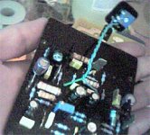
VBE on the little wire...
VBE on the little wire...
Attachments
Yeah... Andrew t is rigth... using resistances we need enormous heatsinks.
And also fan blowers..... i have used this way to make it simple and cheap...but i have faced problems, as constructors normally do not know exactly "what is the size of a big heatsink"...i have suggested but this do not fits constructor needs i think.
Because of that i decided to suggest people to use the more safe VBE multiplier.
And this will be turned "standard"..because the thread experience told me that.
I am using resistances here, in my home.... and full power..but my heatsinks are enormous..more than twice the needed size..also i have a fan to help me.....not using this resources...and beeing experienced, the amplifier can burn itself because of temperature increasing without stop.......well...will stop when burned.
Andrew T is rigth..... i do not love him because he is a theoric guys..but i have to accept that they are needed...at least one..ahahahahhaha!
Resistances, as standard will be banished soon..also the flexiblity related transistors...we gonna construct a safer sittuation.
Graveyard.....hummmm....graveyard?.....i think you know have something to adjust with big fat Charlie....Mr Andrew.
Sorry Nordic...but he is rigth....without VBE multiplier only unders controled sittuations...means..in my home.... as i have 46 years constructing those things and i know how to use them without VBE multiplier...as this is not "universal" knowledge..and i cannot make people experienced as this takes too much time...i will revert the bias system an a humble way..
Very happy as Andrew cooperated.
regards,
Carlos
Attachments

- Status
- This old topic is closed. If you want to reopen this topic, contact a moderator using the "Report Post" button.
- Home
- Design & Build
- Parts
- using light bulbs when testing new DIY project