Hi Jcx,
"What exactly do you think needs Correction in Linear audio coupling applications?"
Maybe you misunderstood my sentence, my point is: it would be nice to be able to remove capacitor(any component/circuit in fact) distortion/nonlinearity , perhaps compensating it somehow, but too bad that for caps in coupling application, there's not much we can do about it. and it's too bad that while Bob can reduce capacitor error in his application, we can not do much other than changing capacitor type.
"unless you have some new data showing ppM frequency response variations are audible,"
I never mentioned that miniscule frequency response is audible in this thread. Anything can sound different and not because of frequency response")
Best regards,
Hartono
"What exactly do you think needs Correction in Linear audio coupling applications?"
Maybe you misunderstood my sentence, my point is: it would be nice to be able to remove capacitor(any component/circuit in fact) distortion/nonlinearity , perhaps compensating it somehow, but too bad that for caps in coupling application, there's not much we can do about it. and it's too bad that while Bob can reduce capacitor error in his application, we can not do much other than changing capacitor type.
"unless you have some new data showing ppM frequency response variations are audible,"
I never mentioned that miniscule frequency response is audible in this thread. Anything can sound different and not because of frequency response
Best regards,
Hartono
... we should start with the glossary: http://www.diyaudio.com/wiki/index.php?page=Audio+Glossary ... no entries for capacitors at all or the associated terminology ...
A simple "door opening" entry would work ... or a reference to the hydraulic model related to a capacitor ...
A simple "door opening" entry would work ... or a reference to the hydraulic model related to a capacitor ...
I don't think anyone suggested potential sonic differences between caps are due to frequency response aberrations. Too easy to measure.
Re: the term 'ground' was just useful shorthand to describe the common practice of putting a very low AC impedance - the capacitor - across the error voltage being measured. Every test I recall seeing placed a resistor in series with the cap, tied the other cap end to ground and drove the resistor end with the generator, measuring mid-point. Potential spuria generated by the cap are shorted by the cap. A good representative test for some applications like PS filtering but of limited value for coupling.
Re: the term 'ground' was just useful shorthand to describe the common practice of putting a very low AC impedance - the capacitor - across the error voltage being measured. Every test I recall seeing placed a resistor in series with the cap, tied the other cap end to ground and drove the resistor end with the generator, measuring mid-point. Potential spuria generated by the cap are shorted by the cap. A good representative test for some applications like PS filtering but of limited value for coupling.
" ... Every test I recall seeing placed a resistor in series with the cap, tied the other cap end to ground and drove the resistor end with the generator, measuring mid-point. Potential spuria generated by the cap are shorted by the cap. ..."
... because that's where the electrons are? ... at the ground connection (usually at a more negative voltage).
I would bet there are differences in reactance of a capacitor when the resistor is in series with the cap through the ground connection, thus offering a "longer", more resistive pathway for electron flow ... No?
Attachments
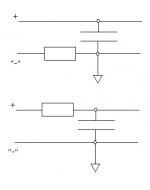
The tests I referred to were similar to your setup #2 and measured across the cap. I was thinking more in term of the below, measured across the resistor. Any capacitor aberrations which manifest themselves as a current will be much easier to measure across a load resistor than across the cap due to the latter's low impedance. Conrad's test in effect was measuring voltage differences to ground caused by cap current flowing through the load resistors.
Attachments
And of course it's a very interesting question what happens when you reduce those resistors and increase the current level. I still question the value of the test, because of what I mentioned above. With increasing current, D becomes a factor, and the circuit is no longer balanced. I can add a resistor to balance it, but only at one frequency. Yet, I was under the impression that D had been sort of ruled out as the "x-factor" for why caps supposedly sound different. Still, it means ESR varies with frequency, and that doesn't seem completely benign. Some say it's dielectric absorption, but others say not. That's actually easier to test (I think) by building up a physical version of the DA model, and making DA really horrible, then seeing if it sounds different. Not enough hours in a day- right now I'm rebuilding an amp and working on my oscillation overthruster, er, sniffer.
This Capacitor type Comparison thread
rdf: " ... I was thinking more in terms of the [attached diagram above], measured across the resistor. Any capacitor aberrations which manifest themselves as a current will be much easier to measure across a load resistor than across the cap due to the latter's low impedance. ..."
mmm .. looks suspiciously like many amplifier inputs = the resistor representing the "load" or input impedence of the amp and the cap blocking any DC offset.
Typical resistor/load values might be from 10K to 250K Ohms. (Wirewound = no? Metal film = ? Other type = ? ...)
The capacitor of course must be good enough to pass through any and all audio information in with relatively flat response ( ~20 to ~20K Htz ? ... 5 to 50K Htz? ... 5 to 200K Htz.?). Hopefully the cap will be good enough to not interfer, distort or otherwise change the audio by its presence. (It is axiomatic for "golden ear" designs to eliminate these caps entirely from the signal path, where possible.)
Thus the whole point of this discussion and thread is to discover the optimum capacitor type for audio application. ... And possibly to include the latest "wise old men" theories and experience regarding selection of capacitors and associated components into a Wiki think piece ... this being, in my opinion, a critical piece of amplifier design and construction knowledge.
Consider, as many of you already know, the use of decent passive components at the imput can make a world of difference at the output ... an extra US$0.50 spent at the input can easily be worth more than US$5.00 spent on corrections at the output. ...
a chart:
Capacitor Type ... Material type and quality ... approximate costs ... Best usage ... ???
============================================================
Ceramic 200 volt ... inexpensive, radial leads ... $0.05 ... high frequency bypass (non audio?) ... etc. ...
Comment? Contributions? ...
Fast Eddy posted:
... because that's where the electrons are? ... at the ground connection (usually at a more negative voltage).
I would bet there are differences in reactance of a capacitor when the resistor is in series with the cap through the ground connection, thus offering a "longer", more resistive pathway for electron flow ... No?
I am not sure whether this is in jest or not
If not, you have a rather bizarre understanding of electrical current, IMO
cliff: " ... I would bet there are differences in reactance of a capacitor when the resistor is in series with the cap through the ground connection, thus offering a "longer", more resistive pathway for electron flow ... No? ... in jest? "
No, not in jest at all. It is not an opinion but a fact that the length of the electron path will certainly make a difference in the results. Distance and timing (speed of electron flow and signal), conductor capacitance and resistance variations ... all resulting in an added contribution to resistance, inductance and capacitance variations ... the RLC time constant being related to phase shift and frequency rolloff, effecting the overall response curve, etc.
(This is but another reason for making certain capacitor types "close coupled" to an op-amp power pins to improve op-amp performance.)
FastEddy said:cliff: " ... I would bet there are differences in reactance of a capacitor when the resistor is in series with the cap through the ground connection, thus offering a "longer", more resistive pathway for electron flow ... No? ... in jest? "
No, not in jest at all. It is not an opinion but a fact that the length of the electron path will certainly make a difference in the results. Distance and timing (speed of electron flow and signal), conductor capacitance and resistance variations ... all resulting in an added contribution to resistance, inductance and capacitance variations ... the RLC time constant being related to phase shift and frequency rolloff, effecting the overall response curve, etc.
(This is but another reason for making certain capacitor types "close coupled" to an op-amp power pins to improve op-amp performance.)
That is so off the wall I don't know where to start!
cliff:
I don't believe that this is off the wall at all. The speed of an electronic signal down a copper conductor is approximately 60% of the speed of light on a vacuum ... If one conductor is a few feet long and another is a few inches, simple calculations will show that the two approximately identical signals would arrive at a common destination at differing times, thus producing a phase shift and associated harmonics and cancelations. (This is one reason of many why ground loops happen.) ...
And, Surly, one should also allow for the contribution of the stray capacitance [differential] of a short wire verses a longer one ... which might make a significant contribution to the overall circuit response ...
These kinds of signal pathway analysis considerations often differentiate a good amplifier design compared to a really, really great design. ... By studying the evolution of op-amp designs over the decades, these manacinations have become critical to the success or not of precision lab equipment, and of course higher quality audio devices ... and is absolutely critical in the design of audio DACs, etc.
One example > check it out: " ... Note that the Timer Tick occurs at 40Khz, the BPF event occurs at 10Khz, and the Display Event occurs at 800Hz. Since the display has eight columns, the refresh rate is 100Hz. ..." ... from: http://www.web-ee.com/Schematics/AudioAnalyzer/AudioAnalyzer.htm ... but not quite, not exactly correct according to figure 8 ... and this device is constructed with careful attention to signal pathway lengths and RLC considerations ...
Fortunately, IMO, all that stuff happens at frequencies where, hopefully, I've squashed everything to near zero.
The circuit looks like an amp input- specifically my amp input, which is 20K. I did do a wideband impedance measurement of the input under power, and it is almost entirely resistive- to my great surprise actually. That's why I've had less interest in lower impedances, and why I don't hear any real differences. With lower impedance, who knows, maybe something audible would show up. I need to get the current projects off my bench before I can do more with this.
Charts are readily available showing the properties of various dielectrics, and capacitors follow those charts pretty accurately- it's hard to screw up Teflon or Polypropylene during cap manufacture, though I do see some variation in D between caps supposedly made of the same materials. BTW, people rave about how good Teflon is, yet I don't see caps offered in any useful value I could use in an amp. What do people do with 0.1uF Teflon caps anyway?
Russian military, tanks I believe. A good relatively cheap alternative for experimentation. Built like tankware too, unfortunately EMP proofed in solid steel with steel pin leads. Those inclined can easily cut and gut them with a standard plumbers pipe cutter. Also unfortunately, that steel case hides the evil of mediocre construction quality in many of the samples I've opened.
Conrad: " ... Charts are readily available showing the properties of various dielectrics, and capacitors follow those charts pretty accurately ..."
Got links? I've seen a couple of these before, but a decent link list might be in order "for the rest of us ..."
" ... it's hard to screw up Teflon or Polypropylene during cap manufacture, though I do see some variation in D between caps supposedly made of the same materials. BTW, people rave about how good Teflon is, yet I don't see caps offered in any useful value I could use in an amp. What do people do with 0.1uF Teflon caps anyway? ..."
Likewise, the only use I've had so far for 0.1 uF Teflon or smaller is as snubbing caps (I continue to rant), close coupled to the power pins on op-amps in parallel with electrlytics on the power rails. But the readily available plastic caps (poly-razzmatazz or whatever) seem to be a) as good or better, b) smaller physically, c) cheaper sometimes by a considerable margin. ...
" ... That's why I've had less interest in lower impedances ..." ... meaning like the input front end of a tube amp?
I searched around for some links, and there are quite a few, but it's disturbing the amount of disagreement between various sources. The only ones I trust are from the sites of the big name capacitor companies like AVX and such. Older engineering reference books (remember those) also have some good info, but not for the most modern materials and construction methods. I have a somewhat incomplete table I'm in the process of fleshing out, and will put up a link to that soon. There's less info out there on dielectric absorption than I'd like, and for all the history of the things, very little real data on paper/oil caps like Vitamin Q and Black Beauties (BBs were considered garbage back then, and sell for $50 each now- go figure).
Well, here's a start. If you've got more into to fill in, or see some obvious errrors, let me know.
some dielectric properties
some dielectric properties
Conrad, your dissipation factor values look close to what I've read for those materials ... as maximum values. Actual values, at least from my measurements, vary considerably and in typically much lower ranges. For instance, I've measured DF of, say, some of those Russian teflons as low as 0.000001, with typical measures in the range of 0.000005 to 0.000025. These measurements are respectively 1 and 2 orders of magnitude lower than the spec you quote.
- Status
- This old topic is closed. If you want to reopen this topic, contact a moderator using the "Report Post" button.
- Home
- Design & Build
- Parts
- Another cap comparison