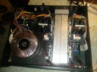
Good Day, I am trying to repair a semi-functional Behringer EP4000. Originally it was making a noise which I was able to get out by fiddling with the ribbon cable but it has another issue. On channel 2, the clip light starts to flicker when turning up the volume until it reaches a point where the light illuminates fully and the sound distorts until the audio signal is completely turned down. When the clip light lights full time the input voltage on the 4580 IC opamp drops from 15v down to 6-7v until the audio is completely turned down, then it jumps back up to 15v but only one one opamp. I don't know whether changing the zener diode at D10 will make a difference as the voltage drop can be measured there.
Channel 1 plays fine without the clip light coming on. I have checked all the output transistors and they measure out fine, and I also swapped out the JRC 4580 with no change to the problem. I have already fixed the ribbon cable problem and I don't know what to check next.
Thanks in advance.
Channel 1 plays fine without the clip light coming on. I have checked all the output transistors and they measure out fine, and I also swapped out the JRC 4580 with no change to the problem. I have already fixed the ribbon cable problem and I don't know what to check next.
Thanks in advance.
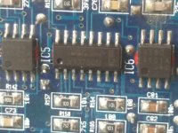
Attachments
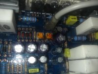
How can I figure out what causes the input voltage drop of the 4580 +15v. When this voltage drops, the clip light illuminates fully and the sound distorts. Can anyone help me figure out this part of this circuit? If I can reverse check the voltage drop, I might be able to identify the cause of the early onset of clip indication.
The EP series is almost a direct copy of QSC RMX. In those amplifiers, and all of their predecessors, bad bootstrap capacitors for the op amp supply can cause the symptoms you describe - early clipping. I've had to replace those in all of my vintage QSC's, and will be the first place I look when the RMX's start malfunctioning.
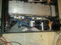
The IC and opamps are located on the underside of the circuit board. After digging around some, what happens now is that the +15v does not drop anymore but the - 15v is the one that drops now. I had switched around the 15v zener diodes on top of the board, and the 5.6v zener diodes on the bottom of the board. The +15v was dropping before, now it's the - 15v that is dropping. I have not found any defective components as I trace the troubled circuit.
Where can the bootstrap capacitors be found?
Where can the bootstrap capacitors be found?
Attachments
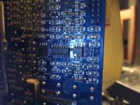
The caps look to the untrained user like bypass caps on the op amp supply and are usually 100 or 220 uf electrolytics. Without them the op amp supply collapses if the output swings more than a few volts. It is a flying rail amp design, which also answers the above question as to why there is only one op amp on that supply. They are independent in each channel, including separate zener derived supplies.
- Status
- This old topic is closed. If you want to reopen this topic, contact a moderator using the "Report Post" button.
- Home
- Live Sound
- PA Systems
- Behringer EP4000 clipping and op amp voltage drop