Hi all anyone know why this amp is not got any out put.
yamaha emx 2000 powered mixer amp
checked all i can & can't find any faults
all the voltages are there going to the connector to the mixer section
all that comes on is the red light & the fan
But when i remove the power supply from transformer to the main amp board
Then you can here the relay click as it should do & you get mixer working
& with head phones you get the sound from cd player pluged into line in on ch 1
but if you re fit the main voltage 71+ 0 71- back in to its plug it all go's off.
tested all the trannys & they seem fine non of the 0.1 ohm resisters have blown
regulator checks out good any idea's folks
You seem to have a blown/shorted power amp section which ap[plies DC to the speaker out.
That triggers the DC protection on and the relays disconnects speakers and maybe something else at the Power Supply.
But nothing further is possible unless somebody gets and posts the schematic.
And even so, you'll have to troubleshoot and repair it.
That triggers the DC protection on and the relays disconnects speakers and maybe something else at the Power Supply.
But nothing further is possible unless somebody gets and posts the schematic.
And even so, you'll have to troubleshoot and repair it.
reply to JMFAHEY
I have the schematic. but where do i start
I've checked all the low voltage & all seems fine. but checks were made with the 71v removed from main board. have checked all the output trannys & none of them are down or shorted. would they give wrong reading if checked in situe
If i can upload the schematic i will. not sure how to?
Attachments
Thanks.
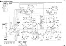
That's something., but the schematic is so small as to be unreadable.
It looks like the preview offered at Elektrotanya, but the real schematic or even better, service manual, is a much larger PDF .
If you have a straight link, please post it here.
If you have the original manual (PDF or ZIP) but it's too large to upload here, upload it to some file server which does nor require registering to see and download files (might require to upload though) and link it here.
And that's the power amp but does not show the power supply, specially the part which feeds the preamps.
What can be seen is that it's a beast of an amp, with what looks like IGBT outputs (industrial transistors) , class H quad rails.
If we get a readable schematic, I'll suggest some (expected) voltage measurements.
Sorry , the EService link is corrupted (or I'm nor enabled by them), currently trying to download from Elektrotanya, wish me luck.
I have the EMX 2000 service manual.
PM me your email and I'll send it to you.
cheers
T
So far, so good.
1) they are not IGBT but Power Darlingtons.
2) not quad rails but 2 ones , although output transistors are in series.
But neither intermediate rails nor switching (nothin to switch) , anyway series transistors sharing voltage improve SOAR a lot.
Actual power transistors have roughly 8 Volts or less (too sleepy to discount diode drops involved) across them all the time, doubled transistors between them and actual rails carry the difference and stand the largest part of dissipation.
EDIT1: I', checking the Power Supply, it's as standard as can be: mains cable > switch+fuse > toroid transformer primary > 2 center tapped secondaries
a) one labelled AC71-E-AC71 which is not 71+71VAC (which would be impossibly high) but "windings which generate _+71/-71 V DC"
Horrible markings because they are very misleading but I found similar ones in Roland amps so I guess labels are for the trained monkeys which build these amps and not for Service Techs. Oh well
So those marked AC21-E_AC21 might be 21+21AC or "whatever's needed for that"
Please measure and confirm actual DC rail voltages and actual windings AC voltages.
Also measure those low AC voltages which supply the preamp, both before and after low voltage fuses labelled F101 and F102 .
2) now you tell us something impossible:
How come?
EDIT2) Thanks zenelectro/T , just got it successfully
1) they are not IGBT but Power Darlingtons.
2) not quad rails but 2 ones , although output transistors are in series.
But neither intermediate rails nor switching (nothin to switch) , anyway series transistors sharing voltage improve SOAR a lot.
Actual power transistors have roughly 8 Volts or less (too sleepy to discount diode drops involved) across them all the time, doubled transistors between them and actual rails carry the difference and stand the largest part of dissipation.
EDIT1: I', checking the Power Supply, it's as standard as can be: mains cable > switch+fuse > toroid transformer primary > 2 center tapped secondaries
a) one labelled AC71-E-AC71 which is not 71+71VAC (which would be impossibly high) but "windings which generate _+71/-71 V DC"
Horrible markings because they are very misleading but I found similar ones in Roland amps so I guess labels are for the trained monkeys which build these amps and not for Service Techs. Oh well
So those marked AC21-E_AC21 might be 21+21AC or "whatever's needed for that"
Please measure and confirm actual DC rail voltages and actual windings AC voltages.
Also measure those low AC voltages which supply the preamp, both before and after low voltage fuses labelled F101 and F102 .
2) now you tell us something impossible:
IF you unplug connector CN102 which comes from the toroidal transformer to the main amp board, you lose +/-71V but you also lose +/-21V so no power to preamp , fan, lights, anything.But when i remove the power supply from transformer to the main amp board
Then you can here the relay click as it should do & you get mixer working
& with head phones you get the sound from cd player pluged into line in on ch 1
but if you re fit the main voltage 71+ 0 71- back in to its plug it all go's off.
How come?
EDIT2) Thanks zenelectro/T , just got it successfully
So far, so good.
1) they are not IGBT but Power Darlingtons.
2) not quad rails but 2 ones , although output transistors are in series.
But neither intermediate rails nor switching (nothin to switch) , anyway series transistors sharing voltage improve SOAR a lot.
Actual power transistors have roughly 8 Volts or less (too sleepy to discount diode drops involved) across them all the time, doubled transistors between them and actual rails carry the difference and stand the largest part of dissipation.
EDIT1: I', checking the Power Supply, it's as standard as can be: mains cable > switch+fuse > toroid transformer primary > 2 center tapped secondaries
a) one labelled AC71-E-AC71 which is not 71+71VAC (which would be impossibly high) but "windings which generate _+71/-71 V DC"
Horrible markings because they are very misleading but I found similar ones in Roland amps so I guess labels are for the trained monkeys which build these amps and not for Service Techs. Oh well
So those marked AC21-E_AC21 might be 21+21AC or "whatever's needed for that"
Please measure and confirm actual DC rail voltages and actual windings AC voltages.
Also measure those low AC voltages which supply the preamp, both before and after low voltage fuses labelled F101 and F102 .
2) now you tell us something impossible:
IF you unplug connector CN102 which comes from the toroidal transformer to the main amp board, you lose +/-71V but you also lose +/-21V so no power to preamp , fan, lights, anything.
How come? I put a connector block on all six wires. & then disconnected the 71+71- wires to the main out puts..but left 21+ 21-
EDIT2) Thanks zenelectro/T , just got it successfully
Ok, so you split the connector.
Everything is clear after it has been said
DC voltage is 1.4142*AC voltage so 1.4142*51VAC is .... ummmmm .... 71VDC?
Measure and post actual rail voltages .
What happens when you plug power amp AC connector?
I can't imagine how doing that cuts power to preamp, except by blowing mains fuse, so please elaborate.
Can't find the headphone out, please search it for me, also the small power amplifier which seems to be driving it, because it does not seem to be hanging from the main speaker outs.
Everything is clear after it has been said
No, it's perfect.51+ 51- ac.... thought this a little low? was thinking it would be 65v
DC voltage is 1.4142*AC voltage so 1.4142*51VAC is .... ummmmm .... 71VDC?
Measure and post actual rail voltages .
What happens when you plug power amp AC connector?
I can't imagine how doing that cuts power to preamp, except by blowing mains fuse, so please elaborate.
Can't find the headphone out, please search it for me, also the small power amplifier which seems to be driving it, because it does not seem to be hanging from the main speaker outs.
Can't find the headphone in on schematic or amp. the input on amp top is the last 1/4 jack on right / bottom. when i plug the ac in for the amp it shuts almost everything off to the mixer section & any output to the headphones has gone. I did get a little activity when i plugged a mic in with xlr but no sound. will check dc rail voltage & post it in
So it looks like it should be 71v dc The voltage i made was 51+ 51- ac b4 rectifier.
So it looks like it should be 71v dc The voltage i made was 51+ 51- ac b4 rectifier.
Not exactly, you should have +71VDC and -71VDC rails at the power amp board, of course at the main filter caps (6800x80) and after the diode bridge.So it looks like it should be 71v dc
There is not a thing such as +51VAC and -51VAC , which you have before the rectifier.The voltage i made was 51+ 51- ac b4 rectifier.
AC does not have polarity sign, while DC does.
And I don't understand how plugging the power amp in turns the preamp off.
Sorry thats my mistake. but the ac from transformer to main board is 51vac on each
----------51vac
--------0vac so this should be 71vac
----------51vac
It may not turn it off..maybe there is a short in this section that put the protection on
But with out this supply connected the mixer comes to life
----------51vac
--------0vac so this should be 71vac
----------51vac
It may not turn it off..maybe there is a short in this section that put the protection on
But with out this supply connected the mixer comes to life
OK, maybe there's a crack nearby and when you plug the 51+51VAC it pushes the low voltage connector aside and preamp loses power or something like that.
You must find what happens to the preamp when the high voltage is connected, something must change.
And also follow the headphone jack backwards to see what powers it.
It's not indicated in the schematic (at least I couldn't find it) but something must drive it.
Maybe some chipamp or even a beefy Op Amp such as NE553x which have higher than normal current capability.
And what voltages do you measure at the Power Amp?
Do you get the +/-71V rails?
Do you get DC at the speaker out?
You have the amp on your bench , so you're the one who has to test it
Good luck.
You must find what happens to the preamp when the high voltage is connected, something must change.
And also follow the headphone jack backwards to see what powers it.
It's not indicated in the schematic (at least I couldn't find it) but something must drive it.
Maybe some chipamp or even a beefy Op Amp such as NE553x which have higher than normal current capability.
And what voltages do you measure at the Power Amp?
Do you get the +/-71V rails?
Do you get DC at the speaker out?
You have the amp on your bench
, so you're the one who has to test it Good luck.
- Status
- This old topic is closed. If you want to reopen this topic, contact a moderator using the "Report Post" button.
- Home
- Live Sound
- PA Systems
- yamaha emx 2000 help find fault