Hello everyone!
I recently acquired a Samson MDR 624 that had been in storage for quite some time. I picked it up because after coming out of storage, the previous owner said that the channels 1 & 2 didn't work but everything else did. I thought it would be an easy fix (maybe replacing the resistors or something along that line) and I thought it'd be fun to take it apart and learn something about how the mixer works (plus if I could fix it I would have an extremely cheap mixer!)
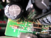
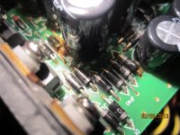
But when I opened it up I found this:

image ru
and

free image hosting
At first glance I thought it was rust, but then I noticed a residue that seems to indicate one of the capacitors began to link. Can someone confirm this for me?
Also if it is a leaking capacitor, will I be able to simply replace the affected parts to get it working again or is it likely the residue has permanently damaged the circuit board after this extended period of time?
Thank you for any help or advice you can give!
I recently acquired a Samson MDR 624 that had been in storage for quite some time. I picked it up because after coming out of storage, the previous owner said that the channels 1 & 2 didn't work but everything else did. I thought it would be an easy fix (maybe replacing the resistors or something along that line) and I thought it'd be fun to take it apart and learn something about how the mixer works (plus if I could fix it I would have an extremely cheap mixer!)
But when I opened it up I found this:
image ru
and
free image hosting
At first glance I thought it was rust, but then I noticed a residue that seems to indicate one of the capacitors began to link. Can someone confirm this for me?
Also if it is a leaking capacitor, will I be able to simply replace the affected parts to get it working again or is it likely the residue has permanently damaged the circuit board after this extended period of time?
Thank you for any help or advice you can give!
Attachments
But that's power supply, not channel.
It might well be some glue or similar gunge put on to stop the capacitors breaking thier legs off with vibration rather than the really nasty stuff that oozes out of overcooked electrolytics- if it's not water soluble don't worry about it (well do, if the electrolytics are old enough to need changing, but not from worries about it having dissolved the copper tracks. Just the problem of getting them off the board).
I doubt whether it'll be resistors that have gone, though. Odds on connectors, pots and then switches, with soldering and actives coming up behind.
It's definitely not a resistor problem. I assumed the reason channels 1 & 2 weren't working was because of a phantom power problem. A few of those capacitors in the picture seem to be in the same circuit coming straight from phantom power switch so if one had leaked, I'm guessing that would explain the problem. I was just wondering if the electrolyte fluid can permanently damage the surrounding area especially since I don't know how long ago the fluid leaked. If it has most likely permanently damaged the chip itself everything is soldered on to then I need to know so I don't waste time replacing all the parts that are affected.
That is glue, not leakage. Larger parts and parts that stick up from circuit boards are often also glued to give them mechanical strength. That helps prevent the solder from cracking.
Can you link us the schematic? If you have no schematic, then contact Samson and get it.
The only way a phantom power problem would prevent channel 1 and 2 from working would be if you connected a mic or other source that required phantom. otherwise nothing will care. Also, if phantom power were bad, all channels that have phantom would be affected.
Now the real question, did you try the mixer, and did you find the channels 1 and 2 to be not working?
If channels 1 and 2 are down, in my experience, that suggets a dual op amp common to both channels. A lot of mixers use dual op amaps set between two channel strips, and the left side of the ICs are used for the one channel and the right side of the ICs for the other channel. An IC goes dead, it kills two channels.
Of course in many situations someone tends to use the first two channels more than the rest, so it is possible it is simply that reason the two are a problem. Dirty insert jacks?
The schematic I've been working with is found in the user manual. Here's the link : http://www.samsontech.com/site_media/legacy_docs/MDR624_ownman_V1sp.pdf
I've been trying to find one a little more detailed but I haven't been able to.
And the reason I thought it was a phantom power problem was because the only channels that don't work are the ones with phantom, everything else works fine including the other input channels without phantom power. But I see what you're saying about things that don't require phantom not caring and yeah those two channels do not really respond to anything. They just add noise when turned up. I did just plug a condenser mic in again while I was playing around with it today, and when the phantom is on you can hear through the mic but there is an abundance background noise and the mic signal is extremely muffled. However, to get any sound from the mic, the channel's volume has to be turned up pretty high.
Thanks for the advice on checking the op amps! I will give that a look over!
I will also check the jacks again, but they looked alright to me the first time through. The only thing that really popped out was the residue stuff that makes the diodes look rusty.
Again, thanks for the input!
Noise can be a bad solder joint, or an open or high value resistor. It can also be the op amp. You can check your solder joints with an ohmmeter from the input pins to the pins of the op amp and from the feedback back to the other input, etc. I would replace the op amp with a socket, so you can experiment without soldering/desoldering more than once. I like phosphor bronze contact sockets instead of tin plated ones. If your schematic diagram doesn't have pin numbers you can download datasheets for the opamps from datasheetcatalog.com. Most mixers use 4558's or RC4560's. Dip packages have plus inputs on 3 and 5, minus inputs on 2 and 6, outputs on 1 and 7. power is + pin 8, minus pin 4.
Last edited:
Your owner manual diagram is a block diagram of the unit, not at all a schematic.
Don't LOOK for a schematic, CONTACT Samson and ASK for your schematic.
Since you have the two side by side channels with the same problem, my money is still on a shared component like a dual op amp.
Don't LOOK for a schematic, CONTACT Samson and ASK for your schematic.
Since you have the two side by side channels with the same problem, my money is still on a shared component like a dual op amp.
As it's two side by side channels, has it been struck on the knobs? - breaking the tracks inside the potentiometers.
I've seen two mixers like that, one a small mixer I bought off Ebay (which presumably got damaged in the post), the other a much larger mixer which had a good number of smashed pots - in a largish circle, obviously been hit by a football, with the centre pots smashed more than the outside ones.
Turned out the lady it belonged to had a young son, and the mixer had been sat in the conservatory
Haha noob move on my end. Obviously I am new to this, but I'm trying to figure it all out as I go. I have tried contacting Samson and am still waiting for the reply. Thanks for the op amp suggestion!Your owner manual diagram is a block diagram of the unit, not at all a schematic.
Don't LOOK for a schematic, CONTACT Samson and ASK for your schematic.
Since you have the two side by side channels with the same problem, my money is still on a shared component like a dual op amp.
Haha kids these days... And the mixer is in great shape (besides from the issue with channels 1&2). Nothing is cracked or smashed and the insides look great as well. At this time I do not think the mixer has been previously dropped or smashed.As it's two side by side channels, has it been struck on the knobs? - breaking the tracks inside the potentiometers.
I've seen two mixers like that, one a small mixer I bought off Ebay (which presumably got damaged in the post), the other a much larger mixer which had a good number of smashed pots - in a largish circle, obviously been hit by a football, with the centre pots smashed more than the outside ones.
Turned out the lady it belonged to had a young son, and the mixer had been sat in the conservatory
Haha kids these days... And the mixer is in great shape (besides from the issue with channels 1&2). Nothing is cracked or smashed and the insides look great as well. At this time I do not think the mixer has been previously dropped or smashed.
It's not something you can see - a direct 'knock' on top of the knobs can break the track inside the pots, so a simple ohms test on the duff channels pots might be in order?.
It's something you'd find during routine fault finding (as I did), but without a circuit it's something that is easy to test for.
Okay, I understand now. As soon as I can I will check. I've had to put the project on hold because of school but thank you!It's not something you can see - a direct 'knock' on top of the knobs can break the track inside the pots, so a simple ohms test on the duff channels pots might be in order?.
It's something you'd find during routine fault finding (as I did), but without a circuit it's something that is easy to test for.
They were quite responsive and very courteous. Here's the real schematic now: FileSnack | Easy file sharingSamson is generally very responsive, if they do not respond by email soon, pick up your phone and call them in New York. Have the serial numbher of the unit handy in case they ask.
If that gunk is acid (capacitor filling) it will be water soluble but glue won't be. Get a wet cotton swab and try cleaning it. If it IS acid it has to be cleaned off. I've seen the acid dissolve the copper traces off the board. Acid must be removed from UNDER the caps as well and if they're leaking they need to be replaced so buy your Silmics or FMs or whatever and get at it.
Remove bad cap, clean the board, replace the cap and clean off the flux.
G²
Remove bad cap, clean the board, replace the cap and clean off the flux.
G²
- Status
- This old topic is closed. If you want to reopen this topic, contact a moderator using the "Report Post" button.
- Home
- Live Sound
- PA Systems
- DIY Mixer Repair. Leaking capacitors?