Folks:
I know that most everybody here posts with their problems so I wanted to take this opportunity to share with you my success story which has been a long time in the making.
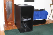
Back in 2005, I purchased a BassTech 7 module from Europe. It was in good condition and at a good price. I then spent the next several years (on and off) searching for the cabinet to put it in. Luckily, in May of this year, I was able to connect with the manufacturers and get a "new" old stock cabinet. After some slight mods to the cabinet to make the module fit properly, I was good to go.
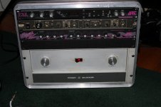
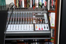
I then picked up a Behringer PMP4000 Mixer and some Peavey PR12's. I coupled those up with a Rane AC23 crossover and Crown DC300A amplifier. After some tweaking the sound is excellent. It even rivals my main system consisting of Klipsch and JBL speakers with Adcom and Crown power.
I have not yet had the opportunity to take it outdoors but I suspect the results will be good. That ServODrive is a monster with 600 watts on it.
-Stu
I know that most everybody here posts with their problems so I wanted to take this opportunity to share with you my success story which has been a long time in the making.
Back in 2005, I purchased a BassTech 7 module from Europe. It was in good condition and at a good price. I then spent the next several years (on and off) searching for the cabinet to put it in. Luckily, in May of this year, I was able to connect with the manufacturers and get a "new" old stock cabinet. After some slight mods to the cabinet to make the module fit properly, I was good to go.
I then picked up a Behringer PMP4000 Mixer and some Peavey PR12's. I coupled those up with a Rane AC23 crossover and Crown DC300A amplifier. After some tweaking the sound is excellent. It even rivals my main system consisting of Klipsch and JBL speakers with Adcom and Crown power.
I have not yet had the opportunity to take it outdoors but I suspect the results will be good. That ServODrive is a monster with 600 watts on it.
-Stu
I'm not familiar with the sub though - does the name ServODrive imply that it's servo-controled? It's an interesting idea and I'm sure q few of us would be interested in hearing about it if so.
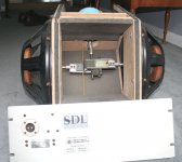
Actually, the ServODrive is not servo controlled, but rather is driven by a servo motor instead of conventional voicecoils and magnets. I have attached a pic of the Basstech 7 module. The blue thing in the back is the servo motor.
Attachments
That ServoDrive unit is a classic as well as the Crown Amp. (I repaired a DC300A yesterday!)
They were used in cinema situations for Sub Bass applications using a pair of 18" steel cones, horizontally opposed and built into a hardwood or ceramic cabinet.
A bit of a pain to set up the null point on some models but useful up to 120Hz.
They were used in cinema situations for Sub Bass applications using a pair of 18" steel cones, horizontally opposed and built into a hardwood or ceramic cabinet.
A bit of a pain to set up the null point on some models but useful up to 120Hz.
Wow, that's weird !!
Does it reproduce anything above, say, 1 Hz?
And only half joking here.
Mass and rotational inertia must be murderous.
Here are the specs:
http://phy6.net/downloads/electronics/Servodrive/Basstech 7/Basstech7.pdf
I currently have the Rane crossoving it over at 80Hz and it sounds amazing!
Very interesting, I'm tempted to cook my own, just to see (hear) what happens.
Upper frequency limit looks too good to be true, but experimenting is king.
Thanks for the idea")
Not to burst your buble, but the engineering that went into this thing is scary impressive. Tom Danley designed it and I must say he did an amazing job. Trying to replicate the actual ServODrive with bass module and cabinet will be quite challenging. From what I can tell, you would have to be both a master cabinet maker and a very skilled machinest.
-Stu
My only doubt lies in the low-mass-rotor motor; the cabinet is .... a cabinet .... , cones/frames/suspensions are piece of cake , in fact I'll start experimenting with an epoxy impregnated cone but if steel is really necessary, that's easy too.
Now if it were Titanium or something like that, well, *that* will be impossible.
But worst case I'd trust more some carbon fiber composite ... and that's well within reach.
Thanks anyway and if you have any suggestion, you're most welcome.
PS: to qualify things: to *exactly* duplicate it, would be difficult; if any because of the absolute lack of useful data (motor specs, drive electronics, exact composition and properties of the rotary-to-linear transfer strip, etc.) but a reasonable approach can be estimated from the pictures, but as an experiment for fun, it's interesting.
EDIT: some specs can already be deduced from the pictures:
1) X_damage is around 40/45mm tops; meaning it can be used , say, up to +/-25mm excursion.
And electronics need to calculate instantaneous cone position very accurately, or it will "bottom out" (or its equivalent) in a catastrophic way.
Or it needs to have some kind of "excursion limit switch" (which may very well be optical) to achieve the same end.
2) the horn where it's mounted is not *that* large, specially if used singly; I recognize that used in quads as suggested it will reach quite lower.
Last edited:
Good to know, thanks.
In my city there's a big surplus (junk? ) dealer, you know the type, a half block open air yard with (mostly military obsolete stuff) piled 20 Ft high, no kidding.
He also has tons of old IBM junk; when I was an empty pockets kid (some 45 years ago) I used to buy "IBM cards" and emptied them by the "burn and slap" method : melting solder with a propane torch and slapping the component side against a table, instant crop of transistors, resistors, caps, diodes, etc.
Also bough the incredible Rotron and Papst coolers.
So he *should* have some old tape transport lying around.
Or so I hope.
In my city there's a big surplus (junk?
) dealer, you know the type, a half block open air yard with (mostly military obsolete stuff) piled 20 Ft high, no kidding.He also has tons of old IBM junk; when I was an empty pockets kid (some 45 years ago) I used to buy "IBM cards" and emptied them by the "burn and slap" method : melting solder with a propane torch and slapping the component side against a table, instant crop of transistors, resistors, caps, diodes, etc.
Also bough the incredible Rotron and Papst coolers.
So he *should* have some old tape transport lying around.
Or so I hope.
If you are truly interested in the ServoDrive, you might join the diyspeakers forum:
The DIYspeakers Forum • Index page
Then search the archive for ServoDrive (members only)
This rather inactive forum is the remnant of the BASS e-mail list of long ago.
Most of the earlier threads have been lost with time.
The DIYspeakers Forum • Index page
Then search the archive for ServoDrive (members only)
This rather inactive forum is the remnant of the BASS e-mail list of long ago.
Most of the earlier threads have been lost with time.
Amazing subwoofer. I remember concerts with rows of ServoDrives across the front of the stage.
Did you happen to get a spare set of belts with the module? They are among the most coveted spare parts for these subs.
Actually, I was able to get in touch with the company that is now supporting these beasts. All of the rubber components are still in good condition as of now. However, I can always hit them up for spare parts.
-Stu
My only doubt lies in the low-mass-rotor motor; the cabinet is .... a cabinet .... , cones/frames/suspensions are piece of cake , in fact I'll start experimenting with an epoxy impregnated cone but if steel is really necessary, that's easy too.
Now if it were Titanium or something like that, well, *that* will be impossible.
But worst case I'd trust more some carbon fiber composite ... and that's well within reach.
Thanks anyway and if you have any suggestion, you're most welcome.
PS: to qualify things: to *exactly* duplicate it, would be difficult; if any because of the absolute lack of useful data (motor specs, drive electronics, exact composition and properties of the rotary-to-linear transfer strip, etc.) but a reasonable approach can be estimated from the pictures, but as an experiment for fun, it's interesting.
EDIT: some specs can already be deduced from the pictures:
1) X_damage is around 40/45mm tops; meaning it can be used , say, up to +/-25mm excursion.
And electronics need to calculate instantaneous cone position very accurately, or it will "bottom out" (or its equivalent) in a catastrophic way.
Or it needs to have some kind of "excursion limit switch" (which may very well be optical) to achieve the same end.
2) the horn where it's mounted is not *that* large, specially if used singly; I recognize that used in quads as suggested it will reach quite lower.
Couple of thoughts here:
Your estimation of xmax is about right. However, there are no sophistacated electronics in the mix. It is just a large blue servo motor that drives 2 15" woofers in harmony. One thing that you could not see, is the cooling fan which sits under the module in the orientation you can see it in the pic. It is a 120 VAC fan and gets its power from the sub amp. Also, on the back of the panel in the rear are some really interesting components. Namely, a full wave bridge rectifer, a couple of inductors, and a cap as I recall. I still have not figured out why they are using a bridge rectifier to drive an AC fan, but it works.
- Status
- This old topic is closed. If you want to reopen this topic, contact a moderator using the "Report Post" button.
- Home
- Live Sound
- PA Systems
- My New PA Setup w/ ServODrive