Ontario
at the hub of the great lakes
i think wg _ski is referring to a tungsten filament lamp you would wire this in series with the horn driver to protect it. it forms a voltage divider i've seen these used in passively x-over monitors to prevent feedback from destroying the diaphram.the net effect is when you've reached the current limit determined by the wattage of the lamp it lights up reducing the voltage the drop across your horn protecting it
probably not much more then 60 to 100 watts so refining our guesstimates the 15's could be 250 rms each and that's not knowing what the realitive efficency of these drivers (1 watt/ 1 meter spl rating) another clue would be looking at the wire size in the x-overs coils in the box that gauge would help determine what was intended. while your poking around see if you can confirm if there wired series or parallel i think it will turn out parallel and count how many coils and caps on the x-over that tell us just how much separation between bands we've got 6 db/octave 12 etc values on the caps too oh and double check to see if there isn't a number stamped on the frame maybe on one of the ribs supporting the magnet the other place might be a small label on the magnet that you might not see if your looking through the opening in the back panel an inspection mirror can come in handy
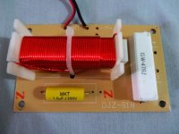
Okay Turk. What I have found is. The speakers were wired parallel and were 16 ohms ea. using my meter but could not get a reading from the tweeter, nothing in there has any info.I have attached a pic of the x-over. Check your inbox.
Attachments
Last edited:
hi eddie
it does appear to be a 6 db/oct x-over with a resistor to pad the horn.was the parallel connection to the two fifteen straight off the jack plate i hope that you've made some notes as to how everything was wired or have only disassembled one. was the x-over input just another parallel feed off the input and it's output direct to the horn?
if you could draw up a schematic of the box wiring and components and get a picture of the input plate(speakon 1/4 in. jacks)
you mentioned not getting a reading across the horn i hope it's not a case of blown diaphragm or are you maybe looking at a piezzo element horn?
thank
turk 182
Last edited:
Ok, The two fifteens were connected in parallel on the x-over. If you look at the pic to the top you will see an "M" with + & - and the Horn was connected by the resistor with the "T" with the + & -. I think the horn is a piezzo. It can screw off so I will change them to drivers.
Last edited:
you may be able to see a high impedance (1/2 meg to 3 meg some can be higher) across some piezzo elements
so we've identified a short coming
well i hope what's been done isn't gonna prevent you from returning these speakers.
but if your still set on rebuilding them as a learning experience let's move on..
so by now not knowing your level skill or understanding what would you say is weak/bad/going on here?
hey eddie
i want to start by addressing you mentioning upgrading the horn driver do we know for sure what it is as in piezzo or bad diaphragm. secondly if it was on a screw thread to the horn it might be advisable to replace your horn/flare and driver on the basis that it might be hard to find something that both fits that thread and is not just a better driver on a cheap flare.
the other thing i was hoping to see if you knew was bad was the x-over and more importantly why? cheap parts aside.
in terms of the 15's for the evolution we're going after they may be fine
did you PM me?
Last edited:
Yes,I PM you earlier today.
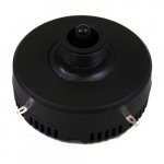
It's a piezo for sure(see attached pic,looks like this).They still work.Looks like an 1 3/8 thread(Horn/Flare looks like one in pic). As for the cross overs,they are only two way,the frequencies will be very limited. When it comes to the 15s as I said in the previous message I will have to hear them in their new capacity first.
It's a piezo for sure(see attached pic,looks like this).They still work.Looks like an 1 3/8 thread(Horn/Flare looks like one in pic). As for the cross overs,they are only two way,the frequencies will be very limited. When it comes to the 15s as I said in the previous message I will have to hear them in their new capacity first.
Attachments
Last edited:
 Please refrain from quoting the entire post just above yours. The quote button is handy, but resist the temptation to over use it! Thanks
Piezo changes everything. IMO, it's not really worth it to bi-amp a speaker with a piezo HF driver. They just don't need any power and wouldn't benefit from it anyway. Input above 28V will kill them, and even short bursts won't give you any more sound. If you do bi-amp, only use something about 40 or 50 watts with your HF, and it will be loafing the whole time. Use about a 5 ohm resistor in *series* with it to keep the amp stable with the light capacitive load that they offer.
I'd just go ahead and screw on a real 1" exit compression driver, and cross at 1.6k-ish. The difference in dynamic capability will be night and day. A 50 watt amp may be enough, but use 100+ to have headroom. A light bulb limiter is a good idea unless you have RMS limiting capability ahead of your power amps, which you should set for an output voltage of 18V (40W, 8R)
I'd just go ahead and screw on a real 1" exit compression driver, and cross at 1.6k-ish. The difference in dynamic capability will be night and day. A 50 watt amp may be enough, but use 100+ to have headroom. A light bulb limiter is a good idea unless you have RMS limiting capability ahead of your power amps, which you should set for an output voltage of 18V (40W, 8R)


- Status
- This old topic is closed. If you want to reopen this topic, contact a moderator using the "Report Post" button.
- Home
- Live Sound
- PA Systems
- CrossOver