Its a rainy day, time for inscrutable problems. I have changed the resistors in the service update diagram on the early PV1.3K amp to the indicated values, and the TIP41-42 TO220 drivers I've picked are 6 amp transistors instead of 4 amp for the oriental OEM drivers so maybe they will be okay for a while. The new resistors cause the load on the U100 op amp pin 7 to be 3 ma (op amp removed) instead of 7ma, which should be okay.
My apologies to cwahls, what I thought was the plus power supply rail collapsing, +1.5, -85, was cause by my 10 ohm load resistor for the speaker interacting with the room heater I have in series with the primary of the transformer. With the 10 ohm 450 W load replaced with a 2kohm 5 W load, the rail voltages are +1.5, -180V, referred to the heat sink which means that the output transistors are doing their job moving the power supplies around against the 4k resistors that center them on the bridge-capacitor PWB.
So how are the NPN output transistors pulling the + rail down to 1.5 without generating any voltage on the OutputTransistor emitter current sense pin 5 of the interboard connector? I replaced some 2.2k sense resistor, I now have 730 ohm between pin 5 (plus emitter current sense) and 10 (chassis ground and speaker negative). My U100 4558's, two different of them, put out 14 V on pin 7 to drive the NPN output transistors hard, caused by -15.5 V on pin 5 of the op amp and -5.7 on pin 6. I spent last night and today verifying continuity from pin 9 interboard connector (speaker + feedback) through 61k to op amp pin 5, and speaker ground InterBoard pin 10 to op amp pin 6. So I think if this happens, Q102 is supposed to throttle back the "cold bias" current to something reasonable based on the voltage coming in from InterBoard pin 5 the emitter current sense. But that is 0 V. I've actually got terminal strips up on the output transistor assembly relaying the emitter resistor top up to where I can reach it on one output transistor, and it is also reading 0 V. So are the interboard pin 8's. I replaced a lot of 1 ohm emitter resistors when I replaced the output transistors, and haven't blown up any OutputTransistors since I checked all the emitter resistor pairs at <1 ohm.
Actually, the cold emitter bias current on both channels is running 0 V, even though channel A makes music of a sort in a car radio speaker. I had hoped changing R210 to 33 ohm would push out the OT base voltage spread a little and make some cold bias emitter current, but I am running 0V on pins 5 and 8 InterBoard connector on both A & B channels. Do I read this schematic incorrectly? aren't IB 5 & 8 sense lines for idle OutputTransistor bias current? Don't Q102 and Q103 throttle back the OT bias current in a sort of negative bias control setup? I've just spent some time tracing through all the components from InterBoard connector pin 5 to Q102 base, and everything reads okay with the ohmmeter, as does the BE junction. Q102 is now a MPS8099 on NPN and MPSA56 on Q103 PNP.
Thanks for looking.
Last edited:
One thing this exercise makes blatatantly obvious is that the floating power supply rails of the PV1.3k and the PV2000 both, subject the driver transistors to 190V! With the B board stuck with the minus rail at -190VDC, it is hard to avoid this teaching point. The TIP41-42C predriver transistors and the motley crew of Motorola 2n6030 (PNP) and NTE60 (NPN) driver transistors are manfully standing the voltage, but if I get the power above 1/2 W like it is now I'm sure something will break eventually. I've got exactly two of On Semi MJE15033s PNP TO220 but for NPN TO220 rated above 200 VDC I've only got some GE Semi D44R1's which have the voltage but are only rated 1 A. That will probably do at 1/2 W, but not 650W. More $$$.
That is not going to solve my stuck B board. Further checks show the quad diode stack splitting the plus and minus predriver base drives from the U100 op amp is okay, and polarized the right direction, taking plus current from Interboard Connector pin 2, returning it on 1. The 400 ohm resistor connecting the + and - driver transistor bases is okay, also, with both TO3 driver bases at 1.1v. With the PNP predriver base at +9.3 V, no wonder no cold output transistor emitter bias current is flowing, the predriver Q204 is stopping everything dead. ????
One is tempted to drill the rivets tying the two emitter lines of the output transistors of the two channels to chassis out, float the speaker minuses from chassis, and connect the center taps of the two power transformer halves together on the capacitor PWB to reduce the 190 volt rails to the 95V shown on the print, but I'm too green to fully understand all the implications. For certain it would mess up the bridged output terminals mode of the amp, which I won't use, but I don't know what other problems it would cause.
Last edited:
Keep in mind that flying rail amps may have funny voltages to ground, but the amp circuit itself is moving with those rails. In other words, in a "conventional" amp, if there were 50v rails, then drivers and outputs can be subjected to 100v - the sum of the two rails. The flying rail is no different. Parts in the drive train can be subjected to the total of the two rails. Those rails are not referenced to ground, they are referenced to the load.
If the output is pulled over to one rail, then the opposing rail will have been pulled along with it.
DOn't think of redesigning the circuit, it is fine like it is, at least once it is repaired.
If the output is pulled over to one rail, then the opposing rail will have been pulled along with it.
DOn't think of redesigning the circuit, it is fine like it is, at least once it is repaired.
Thanks for the extension of my limited knowledge. I took money to the bank account with the debit card today to order MJE15032, and am dutifully putting the last MJ21195 and MJ21196 on the TO3 driver spots tonight. Both PCB's, even the one that works.Keep in mind that flying rail amps may have funny voltages to ground, but the amp circuit itself is moving with those rails. In other words, in a "conventional" amp, if there were 50v rails, then drivers and outputs can be subjected to 100v - the sum of the two rails. The flying rail is no different. Parts in the drive train can be subjected to the total of the two rails. Those rails are not referenced to ground, they are referenced to the load.
If the output is pulled over to one rail, then the opposing rail will have been pulled along with it.
DOn't think of redesigning the circuit, it is fine like it is, at least once it is repaired.
My only previous transistor amp repair was a dynakit ST120, which had 80V single rail and quasi comp allegedly 2n3055 output transistors- 60V rated in 1966. They got away with it, right? Probably not, they were probably specially selected 2n3055 transistors - the burned TO3 hulks had an RCA 5 digit number on them.
Last edited:
I have seen any number of amps with 2N3055 selected for 100v curves.
There are certain old Fender models with a schematic specifying 50v filter cap in the bias supply, and in fact installed in the amp, with the same schematic calling for -55v on the supply. But i am not aware of any glaring errors like that in the Peavey amps.
There are certain old Fender models with a schematic specifying 50v filter cap in the bias supply, and in fact installed in the amp, with the same schematic calling for -55v on the supply. But i am not aware of any glaring errors like that in the Peavey amps.
Well, I figured out some things on my own but I need help again on the PV1.3k with bad channel B. I actually had it running playing music from a radio for half an hour on both channels. I had 32 ohms on the 120 vAC (+-75 rails), 10 ohms@450W on each output, with car radio speakers clipped across 5 of the 10 ohms on each side(e caps in series with car radio speakers). Then Pop! back to -93v, +2V rails. I've got the triacs removed until it works a couple of hours, since all they do is burn lands off the OT board anyway, they don't blow the breaker.
When stuck with DC out on speaker +, op amp U200b (4558) is putting out 6.2VDC into the diode stack and 4.2v into the base of the NPN pre-driver, no wonder. The output transistors are fine, with the driver board disconnected the rails are +-75 at the OT's and the emitter current on the one I have test points run out on is 0.00V. As soon as I plug the driver board in, back to -2+93 rails. The op amp has -15 into pin 5 and -6 going into pin 6 (minus) So V+-(V-) should be -15v-(-6v)=-9v? * A factor =minus 15 V out, right? As soon as I pull the op amp, the rails go back to normal. changing the op amp doesn't help. The capacitor between pins 5 & 6, C208 was changed to a 1000 v rated 22 pf cap, which made it start working before. Q200 & Q204 predrivers are ON semi MJE15032-33. Drivers are survivor MJ15024-25 from the old OT's. I did have it working with a MJ15025 and a MJ21196, but pulled the 21196 to not violate your "matched technology" up and down transistors rule. OT's are all MJ21195-96, tested for Vce and the odd one rejected.
Ouput Connector pin 9 is -43, pin 10 is 0, Op amp pin 8 is +15.5, pin 4 is -15.5. I've checked the current out of pin 7 of the op amp to make sure no predriver transistor is blown, and I'm only getting 3 ma into a 1000 ohm resistor then the ammeter then emmiter line of OT ground. The predrivers read okay for the double diode test with the ohmmeter, anyway. I've traced R235 (4.7k) and CR 220 out to the ground at pin 10, they are okay. C208 is still reading infinity on the ohmmeter (@2v). The 61k resistors read right. All the electrolytic caps are new, and I had AC radio beats going into op amp pin 6 when it was working. Please ???????
Last edited:
Your output stage is working. You disconnected the driver and it centers OK, right?
You replaced the op amp, so we assume it is OK. The poor little op amp is trying its heart out to correct a problem in the system loop.
Remember, this amp has flying rails, the center tap of the power supply is NOT ground. What happens is the system more or less drives into ground, pushing the rails back and forth, and the center tap moves with them, feeding the speaker. So when the rails go off the end, it means the amp is skewed over to one side. It is the same thing as putting DC on the output of a conventional amp, we are just looking at it from the other direction, so to speak.
You gave us a few op amp voltages on pins 5 and 6, but you left out the MOST important ones. What voltages are on the IC power pins, pins 4 and 8? Note that +16 and -16 come onto the board left side driver page, but the op amp in question runs on +16A and -16A. Look closer on the left of that oage and see that the 16A rails are simply the 16v rails run through isolation diodes. SO verify that even during failure mode you still have good +16A and -16A, AT THE IC. If it is going away, then look back at the plain 16s coming on the board, and if not right, back to the small power supply board.
Look at your circuit, you have -6v on pin 6? How did it get there? Pin 6 is a resistor to ground, isn;t it? Pin 5 is a sample back from the speaker output. Offhand I see no other places for any voltage to get on pin 6 other than through the IC. All the more reason to look for missing or funny power rails to the IC.
You pull the op amp and the amp instantly settles where it ought to be, so again, the amp is working, it is being TOLD to more off center. To me that means everything to the right of the op amp is probably OK.
Thanks for listening. This morning I pulled the 4560 op amp and the 3080 transconductance amp, no improvement. Then I changed the TO3 NPN driver, Q207, worked okay for 1 second then pop! rails off center.
Then I checked the U200 pins 4 & 8 without op amp, -15.1, 15. Then with op amp, installed and and rails off center, pin 4 -15.1, pin 8 +9.4V . So bingo, you're right as usual. Will check the voltage regulation stack again. With the + rail at 2.1 V I'm a little vague how the op amp V+ will regulate to + 15, but will study the schematic.
The minus of my meter is on the emitter line on the O.T. assembly, I put a solder terminal strip over there to measure the emitter resistors of a PNP and NPN resistor directly against the emitter ground line. That terminal reads 0 ohms to the pin 10 output connector but is easier to clip on.
Update the 47 ohm resistors from the +- rails go to CR200 and CR216 the B 16v diodes, and those diodes read 560 ohms forwards and build up backwards to 1999 ohms as the capacitor charges up. Is there supposed to be some connection from the C16v supplies (from the power board through P204) to the B16V supplies? That power board 16v stuff was all blown up when I bought the amp and I replaced it, but I read the schematic that the supplies for the 4560 from P204 and the supplies for the 4558 from the OT rails are separate.
Last edited:
****, C218 on B driver PWB, the -16V supply filter cap, was upside down. Just like it was when I bought the amp, and upside down from C118 the analogous cap on A driver PWB. Was working a while since it was a new rubicon 50v cap, was always supplying the 4558 op amp - rail (or the short through the op amp from output to rail was from the 61k feedback resistor at -90 v), but the -16 supply was starving Q204 the PNP predriver apparently. What was collapsing was the op amp plus supply, because the main supply rail was at 2v with the NPN trying to make a little bias current while the the PNP side was dry of supply current. I was wondering why I was getting only 0.1 V emitter current output transistor voltage on the NPN output transistor side, with the + output transistor rail collapsed to +2.5 V. Has worked on both channels a whole 5 minutes now with plus and minus rails at +-75v (with the room heater still on the AC line) . Bias current OT connector pin 5 is -.04 v, pin 8 is .06v. Seems safe. Now on to producing a safety circuit that really works instead of burning the lands off the output transistor board to the triac!
The safety circuit is going to use the diacs, or bidirectional switch as some people call it, to turn off the triac that hold a normally open speaker relay closed. I was going to use 2 triacs to do a logic inversion so I don't need a 24 VDC supply (and transformer) but I can't really figure a way to do inversion in 120 VAC logic. So there are going to be 4 optoisolators from the diacs on the "flying speaker ground" to the relay turnoff logic on the wall plug neutral. The relay may be too slow to prevent speaker fires, but I have also put 25 amp DC fuses in the supply rails. This will cause DC on the speaker if one fuse blows due to a bad output transistor, but the relay will come along and clean up the mess in a quarter second or so if the other fuse doesn't blow too.
The safety circuit is going to use the diacs, or bidirectional switch as some people call it, to turn off the triac that hold a normally open speaker relay closed. I was going to use 2 triacs to do a logic inversion so I don't need a 24 VDC supply (and transformer) but I can't really figure a way to do inversion in 120 VAC logic. So there are going to be 4 optoisolators from the diacs on the "flying speaker ground" to the relay turnoff logic on the wall plug neutral. The relay may be too slow to prevent speaker fires, but I have also put 25 amp DC fuses in the supply rails. This will cause DC on the speaker if one fuse blows due to a bad output transistor, but the relay will come along and clean up the mess in a quarter second or so if the other fuse doesn't blow too.
Last edited:
Anybody bored? Waiting for the customers to shovel out the snow and get out?
I got both channels of the PV1.3k working, and figured out why channel B had no power to it (wires tied off by repairman) and printed stickers saying "Do NOT use channel B". The output kept whanging to +75 V on the output with any op amp in the U100 spot (4558) any time I touched anything on the input circuit with a meter. But stable as a rock at 0 v with no op amp installed. Turns out the pin 6 of the U100 socket had a bad solder joint, probably left the factory that way.
So anyway, with the output at +75v and a room heater in series with the wall AC, Q102 doesn't do anything. That is with a 10 ohm resistor on the speaker output, with a 4 ohm speaker in series with 3000 uf AC capacitors bypassing 5 ohms of it. So if Q102-103 don't limit DC idle output transistor current, what do they do? The sense path from Q102 base to the emitter resistors is continuous, I probed the trace on the output board. The several of the burned 2200 ohm sense resistors were long replaced, the sense line to emitter line is 700 ohms.
I see from this thread on an Ampeg bass amp http://www.diyaudio.com/forums/solid-state/224159-ampeg-svt-3-pro-power-amp-3.html that Q102 and Q103 might be "VI limiters". So what does it take to get the base of Q102 up to 0.6 v and actually limit the drive current to the driver BJT's? Maybe I still don't have enough load resistors on the speaker jacks to test out this part of the circuit?
On an aside, I've traced out the AC power scheme enough to figure out that the triac on/off "relay" is switching the neutral side of the AC power, and the circuit breaker may be on that leg, also. No wonder there is no CSA rating on the backplate. Anyway, I wanted to put a MOS spike supressor on the AC so I don't have to unplug it everytime I leave the house when it might storm. A poster on another thread warns me these fail shorted. SO, to protect the hot line from 1000 V spikes from lightning, I have to install another fuse, on the hot input wire. Fortunately, there is room by the input splice board. Maybe units sold in Canada got an extra circuit breaker up in that dead area? I'm trying MDL30 at this time because I have some, but will put some MDL20 fuses on my next out of town order.
Last edited:
Q102,103 are lmiters, but they are not there to limit idle current necessarily. They work by shunting the signal at the bases of Q100, 104, the predrivers. If the output is slammed over to a rail, they can't do much about it.
If an output xstr shorts, it often takes out the emitter ballasts, those pairs of 1 ohm 5w. When those open, that leaves the p[oor litle 2200 ohm resistors as the remaining current path, and they burn up.
75v on the output, with 10 ohms across? Your speaker was capacitor isolated, so while it may show its impedance to the signal, it wonl; show any resistance to the idle current. In any case, I figure that 75v is the peak of about 53vRMS if it were a signal, and into 10 ohms I get about 280 watts. I don't expect this amp to be limiting anything at 280 watts.
You want to get 0.6v on the base of Q102? Then you need to get that much voltage dropped across those pairs of 1 ohm. But wait, there's more. Those 2200 ohms act along with the diode and 100 ohm across the BE of Q102. They form a voltage divider. SO get enough current flowing through those 1 ohms to make enough voltage drop to make it through that voltage divider to turn on Q102. Takes a lot.
Put your MOV across the transformer primary. That will protect the circuitry, but still be on the amp side of the breaker. NO new fuses required.
I have attached a crude hand drawn AC wiring for this amplifier. MAybe it will be useful to you.
Attachments
Thanks for the AC schematic. I wasn't sure I could avoid dropping screws or standoffs to take the AC board off and trace it out.
Thanks for explaining what a "VI" limiter does. Takes significant current to make this one (Q102,103) restrict base drive current to the predriver transistor, I suppose. Yes, I replaced a bunch of 1 ohm 5 W emitter resistors, too, when i replaced the Output Transistors.
The hand drill is too long to fit in there and drill the hole for the enclosed screw terminal strip on the transformer bulkhead, without taking the transformer out again. To screw the MOV and CL101 turn on surge NTCResistor into. On the back wall they go with the fuseholder, thanks anyway. No more dimming lights at turn on, I hope.
Last edited:
Enzo will be along eventually, but I would be suspicious of 2 ohms per side at 1000 watts per side. That would be sqrt(500) or about 22.6? something amps, out of three power transistor pairs. That sort of violates the safe operating area chart of the MJ15024-25, don't you think? You could do that level for a little while which meets the FederalTradeCommission specifications for watt rating years ago, but the heat sink would heat up eventually in a band or bar setting. At 2000 watts would be happier with a PV-1.3k with 5 output transistor pairs per side even though it doesn't carry the rating on the nameplate. The guy that sold me the CS800s was running the SP2-XT speaker in parallel with a 15" woofer horn monitor speaker for 4 ohms on that amp for his band setup. That amp has 4 output transistor pairs.
If you bridged the two sides of a 2K and ran mono, 2 ohms on 6 transistor pair would be more of a sure thing. I don't have any speakers that will take this level and I run my SP2-XT at about 60 W peak 1/8 watt average in my living room, so you really need to hear from band sound men or bar owners.
If you bridged the two sides of a 2K and ran mono, 2 ohms on 6 transistor pair would be more of a sure thing. I don't have any speakers that will take this level and I run my SP2-XT at about 60 W peak 1/8 watt average in my living room, so you really need to hear from band sound men or bar owners.
Last edited:
Im sorry but 50% of that answer is beyond me. The plan was to run 4 kick bins into 2 ohms per channel (350 - 400w each) and it is supposed to be used in an outdoor setting. Do you think its better off run them in bridged mode to achieve this or are you saying that i would have been better off buying a pv 1.3k for running into 2 ohm?
I'm sorry i don't understand the detailed technical side of your answer but it is appreciated regardless.
Many thanks
Mik
I'm sorry i don't understand the detailed technical side of your answer but it is appreciated regardless.
Many thanks
Mik
I suspect the rumors you have heard are right. I think the 2k watts name of the PV-2k is probably a short term rating rather than full time rating. It may have the power supply to deliver the rating, but not enough output transistors. You might get away with 450 w/ch but I wouldn't go much above this full time. This is odd for Peavey; usually the watt ratings in the amp name are very conservative. I'm saying PV-1.3k has 5 transistor pairs, CS800 has 4, PV-2K has three.
If you can get an old CS800x or even a no-suffix model, or a PV-1.3k, it would be tougher in continuous duty PA use at this watt level with one more output transistor pair. All these old amps needs new electrolytic capacitors (if not replaced already), heat sink cleaning and probably new fans to be reliable at this late date. However, they are extremely repairable, well documented on the internet, and parts are available from Peavey and generic electronic distributors, since the part number conversion of Peavey numbers to industry part numbers are not a secret like some other manufacturers. They are easy to get apart and back together, too. The only disadvantage, the transformer models are heavy compared to fancy tech switcher supply competitors or the CS800s which is also a switcher. The CS800s I bought used in 2010 is tripping the breaker, probably needs new power supply electrolytic capacitors like I said. I only paid about $100 for it, though, maybe less. It came as a package deal with 2 SP2-XT speakers (about $350 each on craigslist) a 12 input Peavey mixer, a stereo 16 band equalizer, a Digitech Quad 4 effect unit, 2 speaker stands (poles) a road case, and a 100' 24 channel snake, $1000. All but the speakers, snake, and stands had little cheap problems.
If you can get an old CS800x or even a no-suffix model, or a PV-1.3k, it would be tougher in continuous duty PA use at this watt level with one more output transistor pair. All these old amps needs new electrolytic capacitors (if not replaced already), heat sink cleaning and probably new fans to be reliable at this late date. However, they are extremely repairable, well documented on the internet, and parts are available from Peavey and generic electronic distributors, since the part number conversion of Peavey numbers to industry part numbers are not a secret like some other manufacturers. They are easy to get apart and back together, too. The only disadvantage, the transformer models are heavy compared to fancy tech switcher supply competitors or the CS800s which is also a switcher. The CS800s I bought used in 2010 is tripping the breaker, probably needs new power supply electrolytic capacitors like I said. I only paid about $100 for it, though, maybe less. It came as a package deal with 2 SP2-XT speakers (about $350 each on craigslist) a 12 input Peavey mixer, a stereo 16 band equalizer, a Digitech Quad 4 effect unit, 2 speaker stands (poles) a road case, and a 100' 24 channel snake, $1000. All but the speakers, snake, and stands had little cheap problems.
Last edited:
Right i get you know, the more transistor pairs the better (in laymans terms). Its a shame becuase i had the opportunity to buy a 1.3k instead of the 2k but thought against it because of the markings on the front. Alas the uninformed have made yet another mistake.
Im glad to hear that the amp is serviceable though, i will try to find a good electronics shop to have a look at it and hopefully with a bit of TLC it will run (fairly) well @ 400w per channel. Thank you for taking time to formulate a reply that i can understand, you have been very helpful. Next time i will go for a 1.3k if i have the chance!
Regards Mik
Just my opinion.
I don't think it is fair to an amp to just count the transistors. I learned a valuable lesson many years ago working on a Carver PM1.5. Nice amp, I like them, though I hate working on them. I found out the hard way that that amp will not drive a sine wave into a load at full power for any period of time. I caalled Carver and discussed it, and they told me that was normal, the ampo wasn't designed to amplify sine waves, it was designed to play music. And in fact, the amp would amplify music all day long at full power. Just not sine waves.
Music is not sine waves, music is a periodic sort of signal. Those thousand watt kick drum peaks are just that, peaks. And at a half second apart, they give the amp plenty of time to rest. So your 22A is about 8A per device if there are three of them. Those are MJ15024, which are 16A devices. Does 5 transistors have potentially better current potential? I suppose it might, but the question is not that, the question is whether the 3 transistors are up to the job.
In the decades I have been involved with servicing Peavey gear, I have never had a reason to doubt their specs on anything. There are plenty of people who just object to 2 ohms no matter what. 40 years ago, I heard the same things about 4 ohms. If Peavey says an amp will run reliable at 2 ohms, I am inclined to believe them. They do have other products with 2 ohm rating where the 2 ohm output is reduced considerably. IN other words it is OK to run 2 ohms on those as long as you don;t expect full output. They do that because a lot of people don't understand that simply connecting 2 ohms to something doesn;t stress the amp. It is only when you try to put a lot of power into the 2 ohms that stress might occur.
And that brings me to another point. The amp is rated to put out 1000 watts into 2 ohms per channel, but are you going to be asking it to do so? If your speakers are rated to 500 watts, that does not mean they will be taking 500 watts, it only means that is the maximum they can withstand. You may not ever drive them that hard.
Okay, I'm ready to document my proposed fix for the PV1.3k melting the triac off the PWB when an output transistor shorts, instead of blowing the breaker. I repaired the trace with a 16 ga wire, then watched it melt that wire. No more relying on the triac crowbar for me, I paid 6x for each SP2-XT speaker what I paid for the amp ($600 for 2 speakers, $55 for a blown amp).
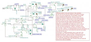
See the circuit diagram below. With the flying power supply rails, most disconnect circuits won't work unless you do the digital work with the flying +-16v op amp supply. I was taught to not put analog and digital on the same circuit, so to keep from stuffing two wall transformers for DC in there, I used a lot of $.37 optoisolators.
This circuit draws from the Michael Bean two NMOS fet design, but instead of putting the fets source to source in the speaker hot, I put them in the power supply rails. This takes two photovoltaic optocouplers (fet drivers) instead of one per channel, but might save some $5 output transistors someday if I trip over a speaker cable on the stage. I'm relying on the automotive fuse to detect overcurrent in the speaker line. Further work could use current transformers to measure the current out, and an op amp, But that would require another wall transformer to make op amp supplies, or sucking power off the existing driver or PS boards without adding a connector in a butcher job with drilled holes etc. A heat sink temp sense would be a lot simpler with only one supply and one FET. The existing thermo cutout snap action thermostat is silly but I'll leave it in to avoid buying a $23 roll of blue 10 ga wire. Any thoughts?
Among the things I find questionable, I've never seen anybody put the fets in the rails instead of the speaker line. 74HC74 IC's will source or sink 3 ma, but I don't know if a gain of 3 is enough to drive PN2222 into saturation where they only drop 0.7 v at 10 ma LED current. I don't have LM340-6 or 7806, and the LM340-5 seems to be working fine with a 1n4148 under the common to make 5.6 v, but I don't know if anybody else has ever done that. 6.2 v would be even better on that triple LED in the green/fet driver line on Qbar. I'm getting close to trying it, but it is 10 deg out in the garage where I have to build the fet heatsink/mount bracket, so playing with my new Windows 7 and TINA-TI is more fun today. Pity it doesn't have optoisolators or 74hc74's on the sim. Those current sources as optoisolators are klugy, my apologies, but it beats drawing it out on notebook paper (which I have been using for 43 years) and trying to photograph it where you could read it. My first foray into sim software. I designed stuff for Ford-Aerospace using graph paper for timing diagrams, and a pencil, back before horned toads were exterminated around Houston.
Attachments
Last edited:
Hello I am new to this site and looking for help with a peabey pv1.3k .Problem one and not a problem but on output board the ceramic resistor are not the same that peavey has in the parts diagram .There is .68 ohm instead of 1 ohm and 1/4 watt are 1.5 k and on the drive boards where there is to be .033mf there is 1.5 ohm e 192 standard series resistor any help would be nice
- Status
- This old topic is closed. If you want to reopen this topic, contact a moderator using the "Report Post" button.
- Home
- Live Sound
- PA Systems
- Peavey 1.3k versus PV-2000