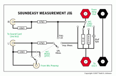
I just bought SoundEasy, and decided to make up a jig so I can leave my wiring intact and twiddle switches instead. So here's what I came up with (with the help of other jigs and probes I've seen floating around.)
Lift times thrust is greater than weight times drag. But will it fly? Comments? Revisions needed?
..Todd
Lift times thrust is greater than weight times drag. But will it fly? Comments? Revisions needed?
..Todd
Attachments
taj said:I just bought SoundEasy, and decided to make up a jig so I can leave my wiring intact and twiddle switches instead. So here's what I came up with (with the help of other jigs and probes I've seen floating around.)
Lift times thrust is greater than weight times drag. But will it fly? Comments? Revisions needed?
..Todd
Looks OK to me. Nice touch to also switch input terminations.
Jan Didden
It will work, but not as well as the original probe concept. I have been down this path. It's basically the Wallin Jig approach. But SE uses "local sensing" approach, with probes best connected directly to the load and sensing resistor. Speaker Workshop (for which the Wallin jig was built) has a nifty calibration procedure that compensates for lead losses, but SE does not use this scheme.
I still use the box that I had designed for a "SE jig", but it has been de-tuned such that it now only switches between impedance measurement and acoustic measurement. I have also included a switch to switch in a series capacitor for protecting tweeters when doing SPL measurements. Also, my box still accepts connections for the probes, connections to the soundcard and the amplifier outputs. But the sensing resistor (for impedance measure) is external now, as are the reference resistors, inductor and capacitor I use for checking setup (they are all loose). This has yielded the most consistent results for me.
OK. Long story short: the jig is a good idea for convenience (a hub if you will), but the sensing resistor should be external and used as per the SE diagrams.
Shaun said:
OK. Long story short: the jig is a good idea for convenience (a hub if you will), but the sensing resistor should be external and used as per the SE diagrams.
Excellent response. Thanks Shawn. Bypassing the series load resistor with the "load" switch will allow me to use one nearer the speaker (or not if I'm feeling particularly lazy) so it's still usable as is.
I have also included a switch to switch in a series capacitor for protecting tweeters when doing SPL measurements.
Me too.
Nice touch to also switch input terminations.
Thanks Jan.
FWIW, here is the one I use with SE.
Thanks dlneubec, looks pretty similar.
..Todd
Shaun said:It will work, but not as well as the original probe concept. SE uses "local sensing" approach, with probes best connected directly to the load and sensing resistor.
Another thought... Using this 'box' with shorter leads to the DUT (say 10-20 cm or so) would probably help here wouldn't it?
..Todd
taj said:Next Question...
How big does the 'sensing' resistor need to be in terms of power dissipation? 10 watts?
And what about the voltage divider resistors? 1/4 watt or 1 watt?
..Todd
It can be as small as 1/4W, perhaps even 1/8W. But I favour larger resistors for the bulk. They're tougher physically and less fiddly.
taj said:
Another thought... Using this 'box' with shorter leads to the DUT (say 10-20 cm or so) would probably help here wouldn't it?
..Todd
IME it's not the lead resistance per se that's the problem, but contact resistance. I use crocodile clips, and usually give them just a bit of a tweak after clipping on to ensure proper contact. My "signal" leads are all of 1.25m long, while the "sense" leads are probably similar in length.
EDIT: Avoid wire-wound resistors. They are inductive, usually. Metal Film is good.
MJL21193,
The test signal is going straight to the amplifier from the sound card then from there to the jig at speaker level. The probes measure the results across the series load reference resistor.
...Unless I'm totally confused (which is always a distinct possibility. In fact, it's usually the case.)
..Todd
- Status
- This old topic is closed. If you want to reopen this topic, contact a moderator using the "Report Post" button.
- Home
- Loudspeakers
- Multi-Way
- SoundEasy Jig - Will it fly?

