Hey y'all, I'm only mildly furious right now. I spend around a month designing these new filters for my speaker project, and the tweeter doesn't work on either! I cannot figure it out for the life of me. All I can tell you is that it's a 4th order Butterworth slope on the tweeter, and a 3rd order Butterworth slope on the woofers. Most importantly, I was doing some localized testing to see what was happening, and I found that the tweeters themselves are fine, and are still fine when given power at the terminal. However, when I applied power to the first inductor location, the power dropped literally about half, and when I applied same power to the 2nd inductor location, the power was nearly non-existent. The woofers work fine though, so I cannot figure it out at all. The only guess I have is that the inductors are too close together (note the tape I put so that they wouldn't touch), but I dunno. Help! ")
-Dave
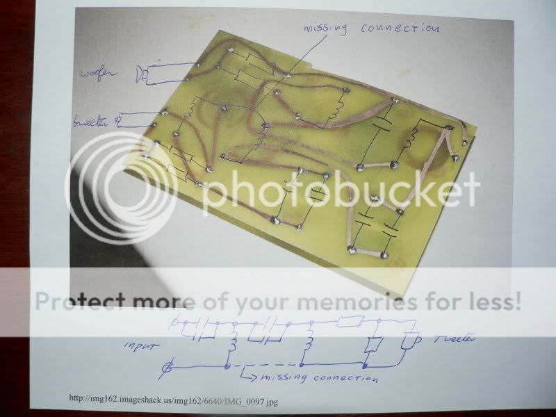
Pics of the x-over if that will help, keep in mind this is my first time with a PCB and etching.
-Dave
Pics of the x-over if that will help, keep in mind this is my first time with a PCB and etching.
An externally hosted image should be here but it was not working when we last tested it.
An externally hosted image should be here but it was not working when we last tested it.
An externally hosted image should be here but it was not working when we last tested it.
An externally hosted image should be here but it was not working when we last tested it.
An externally hosted image should be here but it was not working when we last tested it.
An externally hosted image should be here but it was not working when we last tested it.
An externally hosted image should be here but it was not working when we last tested it.
An externally hosted image should be here but it was not working when we last tested it.
An externally hosted image should be here but it was not working when we last tested it.
No, there are. On the first picture, notice the little sticks of metal. I didn't have any x-over posts, so I just used jumper wire. The ones on the right are the end terminal, and the ones closest on the left are for the tweeter, and below them are the woofer. Seen from the underside, the fourth from the bottom picture shows the right right holes as the end terminals, and the far left ones for the tweeter closest, and the woofer ones furthest away.
1) check your pcb connections with an ohmeter to make sure the pcb matches the schematic - I don't know how many times I have messed up by forgetting whether I'm looking at the top side or the bottom.
2) make sure that you have done a good job of stripping the varnish off of the wires on the inductors before soldering to the board
3) post a schematic of the x-over
4) if all else fails, put it away for 24 hours and then look at it with a fresh set of eyes.
2) make sure that you have done a good job of stripping the varnish off of the wires on the inductors before soldering to the board
3) post a schematic of the x-over
4) if all else fails, put it away for 24 hours and then look at it with a fresh set of eyes.
Schematic may help
could you have reversed components
seen from amp side it should be .... cap---inductor---cap---inductor
what are those resistors
I really dont like xo on printboard like that, easy to make mistakes - also cobberlines looks awfully thin, but that should not be your problem
Furthermore, all inductors should not face the same, but should all be oriented differently, at least the two in the midle
An externally hosted image should be here but it was not working when we last tested it.
That's the schematic.
So what exactly should I be looking for with checking the impedance at the inductors? The traces are .4 ohms (I don't know if that's good or bad). What do you mean by stripping varnish? I've never done that before and I always use the same inductors (18awg Jantzen).
The resistors are as follows
Tweeter: Rp1=1.5, Rp2=30
Woofers: Rp1=1.2, Rp2=10
And I'm pretty sure that I wired it correctly because power goes through the entire circuit, it only starts dropping off on the tweeter side.
I really appreciate any help you guys give me.
again, check the pcb against the circuit with an ohmeter. Make sure you don't have C1/C2 or L1/L2 swapped. The inductors should measure less ohm resistance at DC - compare against the specs.
The varnish is the insulation on the wire used to form the inductors - it needs to be stripped off of the wire with fine sandpaper to expose the bare copper in order to make a solder joint. Some components come with pre-stripped and tinned leads so this isn't always necessary.
Why do you have a pad on both the tweeter and woofer? Seems like a waste of power. For the woofers you could remover Rp2 and replace Rp1 with a piece of wire, then adjust the values of the resistors for the tweeter to balance levels.
I think the tweeter ground is missing on the board.
In the diagram, the "-" of the input, tweeter and woofer are connected together. Unless you have a wire soldered on the top side somewhere, the tweeter connection is missing.
OT: why is there an L-pad on both the woofer and the tweeter?
In the diagram, the "-" of the input, tweeter and woofer are connected together. Unless you have a wire soldered on the top side somewhere, the tweeter connection is missing.
OT: why is there an L-pad on both the woofer and the tweeter?
Okay, I have a + and - input for both the tweeter and the woofer. I have a +and - output for the amplifier. Dunno what's wrong about that, but I do see the missing inductor connection, I'll make the change and will report back with results. Now I remember why I love this site.
Oh, and about the l-pad on the woofer. This is my second crossover for this speaker design, the first was a first order and the woofers were FAR too forward for my liking, so I plotted the circuit again and saw a huge peak in the woofer response. With this circuit, the merge is almost seamless, so I'm hoping for the best.
few posts earlierI think the tweeter ground is missing on the board.....Svante
lemans23, have you tried running the x-over without the "l-pad"resistors for the woofers ?
Do you use the dayton-woofers mentioned in your x-over schematic ?
These metal-cone woofers have a very ragged top-end , at these high frequencies the cone is ringing like a bell.
http://www.partsexpress.com/pdf/295-364g.pdf
In combination with a 1st-order x-over, this might be responsible for the forwardness you were hearing earlier.
The fact they sound much better with your new x-over is probably caused by the fact that you moved from 1st order to 3rd order lowpass, not by adding the resistors.
Klaas
- Status
- This old topic is closed. If you want to reopen this topic, contact a moderator using the "Report Post" button.
- Home
- Loudspeakers
- Multi-Way
- Tweets don't work on my new crossover!