Thanks Joe!
I'm looking forward to hearing from you!
Ific.
I'm looking forward to hearing from you!
Ific.
My apologies, got overtaken by events, including my ClioFW developing a Firewire connection problem and had to be sent to Italy for repair and now $450 later got it back.
When it gets a little warmer, will get the Hamlet work done - so I am next month. As there are many similarities with the Elsinores, I don't think there are going to be many problems and reinventing the wheels. So once started, it should come together quickly.
But it comes down to it most likely being a 4 Ohm nominal design (if it does not drop below 2.8 Ohm it qualifies as nominal), but the actual impedance 3 Ohm flat from 40 Hertz up. Also, it can be current driven by those who want to build the 40 Watt Transconductance Amp.
Cheers, Joe
.
But it comes down to it most likely being a 4 Ohm nominal design (if it does not drop below 2.8 Ohm it qualifies as nominal), but the actual impedance 3 Ohm flat from 40 Hertz up.
.
Hi Joe,
Have you ruled out the potential 12ohm version in lieu of the 4 ohm version? Or is that still open as a possibility?
another entry
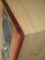
well they are not quite finished yet, but they are singing . at this time i have them braking in in the garage. low Qms, high Fs maybe hard to brake loose since once in the room they will never play to high volumes. one sounded good right off the bat. the other one started harsh with some crackling noises but improved after 2-3 hours. Thank you Joe! I found your approach to design quite agreeing with me, very logical. using four of the same kind calls for a good driver though, but since Troels G. also recommended them for their ability to reproduce vocals, that made up my mind. they are a bit over 65L that I was looking for, mine are over 80L, but hopefully they can make it inside the house without my wife pushing me out. getting them breathing space away from the back wall will be a chalenge though . I attach a few pics for the record. the back veneer and stain are still to come.
well they are not quite finished yet, but they are singing
. at this time i have them braking in in the garage. low Qms, high Fs maybe hard to brake loose since once in the room they will never play to high volumes. one sounded good right off the bat. the other one started harsh with some crackling noises but improved after 2-3 hours. Thank you Joe! I found your approach to design quite agreeing with me, very logical. using four of the same kind calls for a good driver though, but since Troels G. also recommended them for their ability to reproduce vocals, that made up my mind. they are a bit over 65L that I was looking for, mine are over 80L, but hopefully they can make it inside the house without my wife pushing me out. getting them breathing space away from the back wall will be a chalenge though . I attach a few pics for the record. the back veneer and stain are still to come.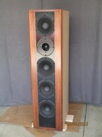
re: bracing
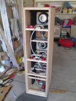
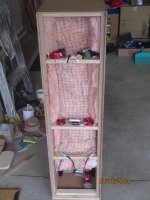
well actually it was Joe who strayed away from the conventional. this makes for a stiffer box, especially if the back gets glued all around and to the braces as well (like these will be when finished). as an added bonus the XO coils can be distributed along the height for minimum interference. normally the chamber behind the tweet would also get stuffed but that does not jive well with Joe's bass concept where all drivers should communicate with the port at the bottom. I also took a risk with an added brace at an angle and moving the port lower and violating a rule there, almost chickened out , but it seems to have worked out well. I am enjoying them. Eventually I may engineer an upgrade to my low end B&W setup to compare against these and see which one is a keeper but I have another project to do before that, so Elsinores should not be contested for the next two years.
well actually it was Joe who strayed away from the conventional. this makes for a stiffer box, especially if the back gets glued all around and to the braces as well (like these will be when finished). as an added bonus the XO coils can be distributed along the height for minimum interference. normally the chamber behind the tweet would also get stuffed but that does not jive well with Joe's bass concept where all drivers should communicate with the port at the bottom. I also took a risk with an added brace at an angle and moving the port lower and violating a rule there, almost chickened out
, but it seems to have worked out well. I am enjoying them. Eventually I may engineer an upgrade to my low end B&W setup to compare against these and see which one is a keeper but I have another project to do before that, so Elsinores should not be contested for the next two years.Bolserst Mod - Stage 1
So, for the past seven or eight months, I have been running the first of the Bolserst modifications. Recall, Stage 1 is the placing of 33R resistors across each of the bass/mid drivers. I have not posted anything earlier as I wanted to live with the change for a while to get a more complete impression on the effects on the overall sound of the speaker.
Admittedly, after seeing Joe's graphs, I was not expecting the Stage 1 mod to make that much of a difference. Boy was I wrong. As tpate advertised, the effect is fairly dramatic. The bass tightened up considerably and the ever-so-slight harshness I felt I had around the crossover point with the tweeter has completely disappeared. The sound is somewhat less bright, but does not lack detail or resolution. The best part was the imaging became substantially better and the overall projection of depth into the room even deeper.
From my viewpoint, with my build, the sound is full, wide, deep, focused and a bit more integrated across the frequency range. They may be a slight tad south of neutral, but not by much (if at all). The sound is somewhat relaxed but again, does not lack any detail or resolution. I can listen to them for hours and hours and hours. I am supremely happy.
At this point, I am holding off on the rest of the mods for two reasons. One, with my build, I am now pretty happy with the results and the next stages take quite a bit more effort to implement. I have to decide how best to test drive the remaining mods before committing to a big change to the cross-overs. Two, I want to experiment with a new amplifier I have just brought online before I make any other changes to the speakers. More on that to come....
Attachments
a bit more about...
I only did the last XO version (Bolserst mkV?) so i would not know about the sound changes over the previous versions. I am still to finish them though, get them inside, use them with my Aleph30 (which I took apart right now to add digital controls), and then listen to them for a while to form an opinion. Eventually I am sure I will also take some measurements to get them speced out, just out of curiosity, but I am not in a rush since that feels too much like work for me.
I only did the last XO version (Bolserst mkV?) so i would not know about the sound changes over the previous versions. I am still to finish them though, get them inside, use them with my Aleph30 (which I took apart right now to add digital controls), and then listen to them for a while to form an opinion. Eventually I am sure I will also take some measurements to get them speced out, just out of curiosity, but I am not in a rush since that feels too much like work for me.
At this point, I am holding off on the rest of the mods....
The next step (stage 2 per Joe's post #1273)
http://www.diyaudio.com/forums/multi-way/97043-elsinore-project-thread-128.html#post3137048
adds the notch filter to remove the small peak at the top end of the woofer on-axis response, and will result in a rather subtle change. It will mainly be noticed by those who toe their speakers in so that they are pointed nearly directly to the listening position. This was tpate's situation. It may also help tame a slightly harsh overall sound even if you don't toe in your speakers that far, but your sidewalls are highly reflective. With pink noise playing, if you can get a helper to connect/disconnect the notch filter, it is easy to hear the frequency range it affects.
I'd say if you aren't bothered by any harshness in your setup configuration, the remainder of the stages probably would benefit you much.
Not that you can't play around...
Elsinore Cabinets for Sale
http://www.diyaudio.com/forums/swap...peaker-project-cabinets-sale.html#post3634741
http://www.diyaudio.com/forums/swap...peaker-project-cabinets-sale.html#post3634741
Woofers for the Excellent JR Mini Speakers
http://www.diyaudio.com/forums/swap...873-5-1-4-nomex-woofers-sale.html#post3634752
http://www.diyaudio.com/forums/swap...873-5-1-4-nomex-woofers-sale.html#post3634752
Someone willing to build cabinets?
Given that I am in Europe and that shipping costs for Elsinore cabinets across the Atlantic would be inhibitive I have to pass on Joels offer. It is however an offer I would gladly accept otherwise since I have no woodworking skills whatsoever.
So, if someone in Holland area (western Germany and perhaps Belgium would probably be close enough as well) is willing and able to build nice quality cabinets for me, please send me a PM. I will be looking for a paint finish that I will apply myself.
Joe Rasmussen Approach to Crossover
Hello to everybody!
Although a member for some time, this is my first post. I take the opportunity to say "thank you!" to all of you participating here for a better audio experience and understanding!
Having read many times Joe Rasmussen's article "Joe Rasmussen Approach to Crossover", I believe that a different set of sketches, concerning drivers' movement when they are connected to Butterworth crossovers, may show in a more accurate way what the author is proposing.
1. Rest point, no comments!
2. In Joe's sketch, both drivers are moving forward. Since there is the BW characteristic 90 degrees phase lag, I propose the alternative sketch. Is there any reason the lag appears in the second quarter of the signal's cycle?
3. In the third sketch the mid driver is still moving forward, its excursion is doubled, although, I think, it should return to its rest point. Therefore, another sketch proposal.
4. The 3rd cycle.
5. The 4th cycle.
6. The fifth stage of movement, concerning only the mid driver as it returns to its rest point alone, since the tweeter has already reached its own in the previous stage.
Do I miss something important?
I would appreciate a lot your comments, especially Joe's.
I just hope that I do not duplicate someone else's same or similar thoughts already posted here. I could not locate something similar in this long thread.
Best regards
Dimitris
Attachments
hello,
I edited and posted the woofer and tweeter model number for mini in the swap meet thread.
http://www.diyaudio.com/forums/swap-meet/243822-joe-rasmussen-mini-monitors-350-complete.html
Shipping waveguides to France is $25 ground
I have only 3 waveguides remaining so extra one for Center: $200 pus shipping..
I have a kit of parts in swap meet in the cabinet sale.. The kit inlcludes waveguides but if someone should be interested in the kit without the waveguides then that will make one more pair available..
Thanks, Joel
Do I miss something important?
I am not sure what the question is?
The sketches you posted do not match what is on my website.
The fact that one driver starts from a resting position equal to the baffle and the other does not, it has to be understood what is represented is a slice in time, not just a signal burst of one cycle.
Let's say that it is a 3KHz sine wave and the crossover is also at that frequency. Let us also say that both MidBass driver and Tweeter have the same Sd, the total surface area (in reality they don't, but that need not concern us for this excercise) and that one driver has a high-pass filter and the other a low-pass filter, single-pole. Then the representation is correct.
This is NOT the starting point of excitation - this is a constant sine wave already in motion. This is a "book-ended" cycle.
Both drivers move forward, being excited by the same signal, but with different but complementary filters. The top driver is now at it's maximum forward posistion. Because the other bottom driver is 90 degrees out of sync, it will be in the middle position and continuing to move forward as the next quarter cycle demonstrates.
The upper driver moves backward and the bottom driver continues to go forward. While in the first quarter of the cycle, where both drivers were moving forwarding, they were summing positive (additive). But in this cycle, they are not adding, but are cancelling. Zero output results.
The next cycle the will again sum.
While they are now moving backwards together, the are still summing - not cancelling.
Now we have the final quarter.

Once again cancelling and back to the original position. We have gone through the entire 360 degrees of the cycle.
So Butterworth cancels out half the output, every second quarter of the cycle results in no output.
But that is of course only the beginning, because in real life the MidBass is starting to beam considerable at 3KHz and it is part of the Tweeter's job description to fill in the failing off axis response in the MidBass, and it cannot do that with any degree of success. So with Butterworth, we can only aim at a flat response on axis, whereas off axis there will be a considerable lack of energy. This means that Butterworth cannot have a flat power response into the room. And yes, it is very much audible, it also cause a perceivable discintinuity between the two drivers. To use fellow loudspeaker designer (and long-time friend) Brad Serhan's wonderful description, "it is about getting the stitch right" and if you get that right, you end up with a crossover that virtually does a disappearing act.
There are other considerations as well. Note that, in the above example, when the first quarter of the cycle, the perpendicular axis is aiming down, and in the third quarter it is upwards? Now consider that indeed the Tweeter and Midbass do not have the same radiating area, can you see that Butterworth also has vertical symmetry problems.
All I am demonstrating is why I avoid doing Butterworth designs.
Cheers, Joe
.
Last edited:
The fact that one driver starts from a resting position equal to the baffle and the other does not, it has to be understood what is represented is a slice in time, not just a signal burst of one cycle.
This is NOT the starting point of excitation - this is a constant sine wave already in motion. This is a "book-ended" cycle.
.
I regret the above were not clear to me...
Now I fully understand and agree with your thinking.
Thanks for the clarification!
Best regards
Dimitris
- Home
- Loudspeakers
- Multi-Way
- The "Elsinore Project" Thread