So this is it?
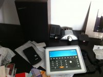
Speaker with no filter connected, elements parallell and in series as with filter, Tweeter in phase with Mid&Woofers, 10 Ohm resistor in series with the elements with a total resistans of 13,43 Ohm. Wave generator connected to amplifier and AC-meeter over the terminals where all the elements are connected. Rear part of cabinet stuffed to 80% (or even more - which is far more than shown in the construction drawings) with medium density fill (wool fibre, glass fibre or poly/wool fibre, NOT pure poly fibre) with free air space from elements to port, port 85x85mm inside values. Try to find the lowest AC-value at 32-35Hz by adjusting fill and/or port length.
Speaker with no filter connected, elements parallell and in series as with filter, Tweeter in phase with Mid&Woofers, 10 Ohm resistor in series with the elements with a total resistans of 13,43 Ohm. Wave generator connected to amplifier and AC-meeter over the terminals where all the elements are connected. Rear part of cabinet stuffed to 80% (or even more - which is far more than shown in the construction drawings) with medium density fill (wool fibre, glass fibre or poly/wool fibre, NOT pure poly fibre) with free air space from elements to port, port 85x85mm inside values. Try to find the lowest AC-value at 32-35Hz by adjusting fill and/or port length.
Attachments

So this is it?
Tweeter in phase with Mid&Woofers,
BE CAREFUL:
Do NOT connect the Tweeters to anything while doing this test. You will most certainly damage them.
Other than that, that looks the setup to use.
Fb measuring suggestion...
The old books on speaker design suggest using a 100 to 1000 ohm test resistor. The larger resistor will create larger, easier to see, peaks in the measurements. Also an analog meter works best as these peaks are very narrow and you need to sweep your frequencies very slow to find them. If you use a 10 ohm resistor and a digital meter I believe the peaks will be very hard to find...Dave
The old books on speaker design suggest using a 100 to 1000 ohm test resistor. The larger resistor will create larger, easier to see, peaks in the measurements. Also an analog meter works best as these peaks are very narrow and you need to sweep your frequencies very slow to find them. If you use a 10 ohm resistor and a digital meter I believe the peaks will be very hard to find...Dave
Fb measuring suggestion...
The old books on speaker design suggest using a 100 to 1000 ohm test resistor... Also an analog meter works best as these peaks are very narrow and you need to sweep your frequencies very slow to find them. If you use a 10 ohm resistor and a digital meter I believe the peaks will be very hard to find...Dave
We are measuring Fb here, not T-S... I don't want to sound like I am lecturing, but just to explain.
I think that maybe you are confusing two different objectives here. I wrote computer programs for the old Amiga Computer back in the 80s - in those days there were no programs for measuring Thiele-Small Parameters, so I wrote my own. I am of course in Sydney, the home town where it all started.
When measuring T-S, you have to come up with three frequencies, the two peaks, one above Fb and the other below Fb, and the saddle/Fb. The purpose of using a high value was in fact to drive the VC effectively in current mode, the ideal source was infinite. But since the VC value was much lower than than Series R, and if that R was 100 times larger, that 1% accuracy was attainable. There were two ways to measure T-S, current and voltage, but for high accuracy, the resistor needed to be a very high value.
But... we are not measuring T-S, we are trying to find the Fb of the box. And we are not looking for the two peaks, but the valley, or saddle, between the peaks. To find the narrow peaks, I agree with you, an analog meter is good, but the saddle is very broad and the digital meter may be preferable. Either way, it will work.
BTW, the Fb of a vented box is totally dependant on the box tuning itself, not the drivers. Change the driver, and the peaks may change, but the saddle frequency is determined by the box alone. OTH, with a sealed box, Fb (actually Fc) is dependant on both. Read many books on loudspeakers, but never seen it just plainly stated. Curious.
Cheers, Joe
Last edited:
We are measuring Fb here, not T-S.
BTW, the Fb of a vented box is totally dependant on the box tuning itself, not the drivers. Change the driver, and the peaks may change, but the saddle frequency is determined by the box alone. OTH, with a sealed box, Fb (actually Fc) is dependant on both. Read many books on loudspeakers, but never seen it just plainly stated. Curious.
Cheers, Joe
Crisp as always.
This is it then!!!
First cabinett almost glued together, pictures soon coming.
Joe - What do you say about the changes we have done to the cabinett. Do you want to add them to your construction? I can make some new drawings in that case - I like to add in some way (as with the epoxy WG for EU).
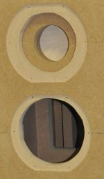
The changes: We have used only 25mm MDF as material, to everything and adjusted the measures in the drawings. We have made the front front baffel going all the way to the sides so you don´t se any end-wood from the cabinett sides. We have made the top and bottom 3mm "to long" on the front side to make them sort of marked instead of just seing the not wanted end-wood that always will be there (if you dont want to have end-wood on the top of the cabinett). As we have the 25 mm front baffel the stiffening panel can hold the whole tweeter without carwing through the whole dept of it. This will allow for a closed cabinett for the thweeter from the rest of the speaker.
Attachments

Last edited:
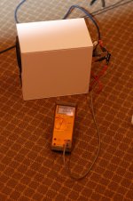
Checked the mini port and test looks good..
At 50HZ I got the saddle and a peak above and below..
Stuffed the box and the saddle was at 47HZ..
I wouldn't have guessed That
At 50HZ I got the saddle and a peak above and below..
Stuffed the box and the saddle was at 47HZ..
BTW, the Fb of a vented box is totally dependant on the box tuning itself, not the drivers. Change the driver, and the peaks may change, but the saddle frequency is determined by the box alone. OTH, with a sealed box, Fb (actually Fc) is dependant on both. Read many books on loudspeakers, but never seen it just plainly stated. Curious.
I wouldn't have guessed That
Attachments
Checked the mini port and test looks good..
At 50HZ I got the saddle and a peak above and below..
Stuffed the box and the saddle was at 47HZ..
I wouldn't have guessed That
Okay that was dumb.. I cut the port to 200mm and put in by mistake..It did seem long..
I cut it to 120mm and now have 60hz..
I checked Fb this morning and I got the saddle at 35 Hz. Does it worth adding stuffing to get a bit lower?
It's not a bad result.
Yes, you could try a bit more damping.
You could also make the port a bit longer if increasing damping is a problem.
If you add up to 20mm length to the port is fine and that should easily do it.
But don't go overboard fussing too much about it - 35 Hertz is just within acceptable range.
Cheers, Joe
Thanks Joe. I have enough damping left so it will not be a problem to try getting lower this way. 20mm more on the port? I'm surprised that I can add as much considering the relatively short lenght of the port.
I added 15mm to mine to get the appropriate drop. You would be surprised how much you can add and how small the corresponding frequency drop that results.
Progress
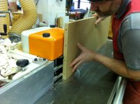
Good to have some quality tools on site.....
We also made the chambre for the tweeter closed by a thinner lid.
Having fun...
Good to have some quality tools on site.....
We also made the chambre for the tweeter closed by a thinner lid.
Having fun...
Attachments
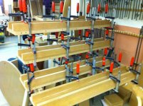
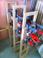
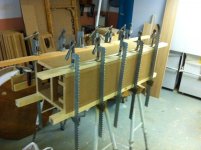
Nice work. Makes my very modest clamp collection feel very inadequate !
I did just happen to find the best carpenter and his site in the area. Nice guy, he help us on and of when we do stupid things, we pay for the time he spend and some minor sum for he letting us spend hours and hours there.... Really Nice
I added 15mm to mine to get the appropriate drop. You would be surprised how much you can add and how small the corresponding frequency drop that results.
I found an interesting study about the effect of port lenght and damping vs Fb. vent tuning
Played with damping and port lenght this morning. Adding damping did not lower Fb, obviously, I didn't add enough... Fb stayed at 35 Hz. I only changed the 25mm thick damping pieces at the front for 33mm thick pieces.
I added 20 mm to the port with tape and Fb got down to 33 Hz.
I added 20 mm to the port with tape and Fb got down to 33 Hz.
Played with damping and port lenght this morning. Adding damping did not lower Fb, obviously, I didn't add enough... Fb stayed at 35 Hz. I only changed the 25mm thick damping pieces at the front for 33mm thick pieces.
I added 20 mm to the port with tape and Fb got down to 33 Hz.
Do you like the sound better at that tuning?
- Home
- Loudspeakers
- Multi-Way
- The "Elsinore Project" Thread