Cant say I follow completely but maybe your saying start with a mounting gap and then one can move it in to touch and out as if prefered..
Correct.
With the TW mounted directly towards the WG there will be no gap at all. Mounted with a wide gasket around the "mounting wall" the TW and the WG will have a gap between them at the inner end of the WG.
This gap can be left totally open and there will then be a "cabinet" in play enclosed by the TW and the WG. Different damping will change the appearance of the TW. You can also add another gasket between the TW and the WG as wide as you like at the inner end of the WG, creating smaller or bigger gap (both in height and diameter of the gasket) as done earlier in this thread.
there seems to be a range of port ODs referenced from 90mm to 100mm, but what is the recommended port internal diameter (ID) for the bass tuning as calculated by joe R.? (which goes with the length of 80mm+-). THX.
These are the recommended lenghts and ID's. You should no go below 82.5mm for ID because the lenght of the port will be too short.
- If ID = 90mm than L = 85mm
- If ID = 87.5mm than L = 80mm
- If ID = 85mm than L = 75mm
Last edited:
Hi everyone,
I'm trying to decide on what I hope will be my last speaker project for the next several years. Right now I have it narrowed down to the Elsinores or Troel Gravesens Jenzen Illuminators (Jenzen-Illuminator) using scanspeak drivers. Overall, the cost would seem to be in the same ballpark (2-3K).
I've been trying to track down an objective and dispassionate review of the Elsinores, preferably by someone who hasn't built them. By all accounts, they seem to be serious giant-killers, but it would be nice to see some arms-length reviews.
Can someone point me in the right direction before I bite the bullet either way?
Cheers,
Joel.
Hi everyone,
Can someone point me in the right direction before I bite the bullet either way?
Cheers,
Joel.
Elsinore Loudspeaker
Just Do It......
Lost radius on WG
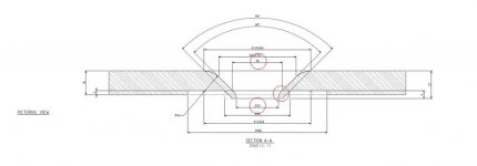
Hi, looking aorund the posts about details for the WG (mostly around #694-718..) I am still having a small trouble. The radius on the outer part of the trumpet is said to be 16mm which looks fine with th measures and lines on the drawing.
The inner curve radius down to the hole does not have a value. The inner diameter is said to be 32mm and there is value 38mm which seem to be the other end (at 45dgr) of the curve. BUT this does not fit. 32 and 38mm will state a radius of 10,24mm which does not fit in the position if the bottom of the hole should be vertical as seen in the picture and match the 45 dgr trumpet.
So either one of those measure are not correct or the inner end of the trumpet is not vertical. Anyone to know from the construction or a real WG? Is this critical.
If we have a vertical end of the trumpet, use a 7,8mm radius on the curve it will fit with a 36,8mm value to the 45dgr part of the trumpet. Would that due?
Attachments
might be somewhat off the current track, but i'm acquiring all the parts for this to start in a couple months. quick question: what exactly does L4 R2 C3 do? is it to quell a resonance at about 60hz? i'm trying wrap my head around that huge coil
The L4-R2-C3 network is there to flatten and linearize the impedance(not the frequency response) in the frequency range around port tuning. This helps achieve Joe's goal of what he call's a "linear current" speaker. What this goal means is that the frequency response would be the same if the Elsinores were driven by a voltage source or a current source. Many tube amps, especially single end zero-feedback designs, have considerable output impedance and can act more like a current source than a voltage source when driving a loudspeaker.
In practice, the L4-R2-C3 will have little if any effect on the sound of the Elsinores when driven with a solid-state amp. If money is tight, you could safely eliminate it until funds are available. But, if you plan to use a tube amp, the network will go a long way in avoiding the tubby, ill-defined bass that often comes with tubes amps driving ported speakers with impedance peaks in the bass range.
Hey!
whats up with the port lengt? when i check it in a box calculator program i get a completetely different tuning frequens, not ewen in the same area as 33/34hz
It should then be 23cm long for a 33hz tuning. Whats with that???
On Joes side it says it should be 80mm long and that give a tuning point of 54.16 hz..
Something is really really wrong here..
SHARKY and I are the one who works together in the project of building a form so that we can build WGs in carbonfibre and epoxy.
SHARKY is the one that takes the part of getting a good mould finished, after that I take over and make them in carbonfibre/epoxy.
We in Sweden wants them in carbonfibre, but it is also possible to make them in glassfibre/epoxy/polyester.
SHARKY and MY goal is to make the available for all other persons that might have interest in a pair.
The price will be reasonable, the price shall cover the materials cost and for my work i will take a real low ammount. I think i have to lay 3 hours minimum for a pair of carbonfibre WGs.
In that stage, the reciever have to laqcuer it himself to get rid of the tiny tiny holes that always appear, i needs to be laquered maybe 3 times before you have clear carbonfibre WaveGiude with that so sexy sweet fibre look!
I can ofcourse laquer and wetslip them self, because they need to get wetslipt between every layer of clear laque but that is a tedious job i reallly dont like but i can do it for payment.
Joels ALU WG costs 160CAN +shipping and a sutable price for these in carbonfibre would be a bit lower than that. BUT, these will weigh maybe 4/500 grams so the shipping cost would be significantly lower.
Carbonfibre is an expensive material and Epoxy isnt especially cheap either.
We want to make them available for all of you out in europa that cant order from Joel just because the shipping for two heavy ALU WGs to europe is totally insane..
I hope someone feels like we are doing a good job making WG available to all??
irext,
Here is a link to Joe's poly material. It is R3.0 in density:
Hope this helps.
Have large problems with damping material here in Europe. Nothing close to what you guys have mentioned in sight here. To continue looking what is the value R3.0 stand for? What we have seen here is things like xxKg/cbm (kilos per cubik mete.
Just want to add, that a large part of the space behind the brace and above the port, needs to be near 'filled' - not completely, but mostly like 80% is nice. And not heavy or too dense material.
The area in front of the brace is 'lined' - so you can see that part of the box is largely 'filled' and partly 'lined' - this gives the alignment a certain resistive property (and makes the box looks larger to the drivers).
In theory, if with the correct port dimension, if the Fb ends up higher than 35Hz, then chances are you do bot have enough fill behind the brace. It is not super critical, but if you can test for the Fb frequency of the completed box and you don't get Fb 33-35 Hertz, then increasing rear fill and/or increasing port length, this kind of tuning can be done.
If anybody wants to test their FB, let me know - and maybe I can make appropriate comment.
Cheers, Joe
Just want to add, that a large part of the space behind the brace and above the port, needs to be near 'filled' - not completely, but mostly like 80% is nice. And not heavy or too dense material.
The area in front of the brace is 'lined' - so you can see that part of the box is largely 'filled' and partly 'lined' - this gives the alignment a certain resistive property (and makes the box looks larger to the drivers).
In theory, if with the correct port dimension, if the Fb ends up higher than 35Hz, then chances are you do bot have enough fill behind the brace. It is not super critical, but if you can test for the Fb frequency of the completed box and you don't get Fb 33-35 Hertz, then increasing rear fill and/or increasing port length, this kind of tuning can be done.
If anybody wants to test their FB, let me know - and maybe I can make appropriate comment.
Cheers, Joe
Thanks Joe,
Yes I have had the design drawings printed in front of my eyes many times trying to figure out what to use.
What we have here is just the ordinary polyester fill which is not at all that good in either damping resonance or enlarge the box. I do have quite an amount of loose speaker damping wool in my basement somewhere since many years but it will not stay in place losely stuffed in the back compartment of the box.
The two most known high end speaker factories here in sweden actually (after contact with them) use the simple "standard fill" glass wool batts as used by many DIYrs me included earlier). But I think I remember someone in the thread having some comments about this material in conjuction with the elsinores.
If finding some loose glasswool that might be an option. just 15-20 mm on the front compartment walls and maybe my wool stuffed between the 50mm back braces covered by someting like 50mm glass wool. If i can find light enough glasswool.
Still trying to find out what the R-value stands for.
It is an Australian Standard. Take a look here:
LINK: R-value - what is it? - Home Insulation Buying Guide - Home Insulation Scheme Review - CHOICE
Generally, the higher the R value, the more like thick the batt will be.
R3.0 is mostly about 165mm approx - this is near perhaps a little high and R2.5 is OK too.
As I said, behind the brace it is largely filled, but don't use anything high in density, and the area above the port. The front of the brace near the drivers are lined.
Typically a vented/reflex box is only lined and sealed boxes are filled. But using some level of fill in a vented box, carefully positioned so that air-flow between the rear of the driver to the port is not restricted, you can get quite a boost of Vb - so that 70 Litres looks a lot closer to 100 Litres. This means the port dimension are affected in such a way that "port calculators" don't work - the port will be shorter by quite an amount for the same Fb.
If you have a sinewave generator (you can often use a computer) and measure Fb using a simple 10 Ohm series resistor and an AC multimeter - it is not hard to do. Aim for fill and port length to get you a 33-35 Hertz target.
Cheers, Joe
Last edited:
It is an Australian Standard. Take a look here:
LINK: R-value - what is it? - Home Insulation Buying Guide - Home Insulation Scheme Review - CHOICE
Generally, the higher the R value, the more like thick the batt will be.
R3.0 is mostly about 165mm approx - this is near perhaps a little high and R2.5 is OK too.
Cheers, Joe
Great link.. It explains it all as there where a matrix with different materials, including glass fibre batts. Makes it easier to start measuring.
Br
//H
Interesting ... Australian R values are significantly different than North American. Aussie R3.5 (140 mm of medium density fibreglass) is equivalent to what 'we' (North Americans) call R20, which is the standard batt shoved into a 2 x 6 stud space (2 x 6 is actually 1.5" by 5.5")
If you have a sinewave generator (you can often use a computer) and measure Fb using a simple 10 Ohm series resistor and an AC multimeter - it is not hard to do. Aim for fill and port length to get you a 33-35 Hertz target.
Cheers, Joe
Never measured this before, but now i will. Computer output with sinus wawe to amplifier and to speaker. Measuring the resistance (of the whole speaker or just over the base elements?) over + and - poles vith the multimeter in series with a 10ohm resistor (why?) or how do you mean?
When the resistans increase to its top i have the speaker resonance Hz????
Make sure you have no crossover attached. Just drive the four driver together by connecting jumper. Use a 1.5V battery and make sure they all move out together (or in together, depending on which way the battery is turned around). That makes sure they are all in the same phase. Now apply the signal. Using the series resistor, it is most common to have the AC meter across the speaker terminals. Below 100 Hertz you should have two peaks and a saddle in between. The higher peak may be around 70 Hertz and the lower peaks in the 20s of Hertz. The saddle, where the meter reads lowest, will be the Fb of the box and around 33-35 hertz.
Cheers, Joe
Cheers, Joe
- Home
- Loudspeakers
- Multi-Way
- The "Elsinore Project" Thread