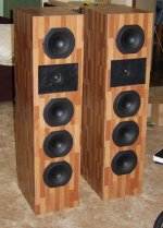
danieljw said:Finished Boxes
(Thanks for Rob, Helmuth, Tinitus and Obviously Joe's Advice)
Havent listened to them yet I am still building the crossovers.......
Will be a week or two because of work commitments...........
-Dan
WOW! They look really nice. Good work.
You are right about soldering the tweeters, but not unique to just these tweeters.
Joe R.
Joe Rasmussen said:
Take a look at this post:
www.diyaudio.com/forums/showthread.php?postid=1161906#post1161906
Focus on the Vifa XT25 Tweeter - incredibly flat ON axis (reputably goes up to 40KHz), but how the OFF axis response is dreadful (almost -20dB @ 20KHz).
I used this tweeter in Mark 1 version of the Elsinores with waveguide. The OFF axis response was hugely improved by the waveguide. Others have noted this as well. Indeed I mentioned the Lipinski L707 earlier that also uses XT25 and has been measured with an improved OFF axis response.
The HDS tweeter is a very different kettle of fish. If you haven't read the whole thread, you might find it interesting, starting here:
www.diyaudio.com/forums/showthread.php?s=&threadid=97922&perpage=25&pagenumber=1
Joe R.
Thank you Joe.
Its surprising how the waveguide improved the off axis performance.
Did you find a similar outcome with the Mark 3 (stepped felt) version where I'd assume the felt would absorb some of the off-axis energy?
David Gatti said:
Its surprising how the waveguide improved the off axis performance. Did you find a similar outcome with the Mark 3 (stepped felt) version where I'd assume the felt would absorb some of the off-axis energy?
Yes and no. The felt being absorbent is not so much the whole point here, it is as much the shape that is important. But felt is good stuff to use and reasonably easy to get results.
The strengthening of the off axis response I believe is due to boundary effects. The way I see it, it will stiffen the air impedance enough to lift the output closer to the boundary (which is in line with the off axis). The off axis output of the tweeter itself is not increased, so it has to be an acoustic Z factor. I would love anybody reading this make any comments - and any explanation they might have. Think of folding the sound forward rather than absorbing it or dissipating wide on a flat baffle. But that 'forward' is still off axis and in fact reinforces it. I am trying to paint a word picture.
At the bottom of the passband, the waveguide has an additional effect. It has a similar result as if increasing the surface area of the tweeter. Again an acoustic Z factor, but a different type. I believe this is desirable as the area of the midrange cone is relatively larger, in fact much larger, than the tweeter at the frequencies where they intersect (crossover), even allowing for the midrange cone decreasing its radiating area as it gets closer to the crossover (it can only do so much as the beaming effect gives it away). It allows for a more gradual acoustic hand-over between the drivers. So the gradual decrease in radiating area is just that, more gradual and less obvious to the ear. Remember, it has to go from wide down to just 1 inch (25mm) into the lower and mid treble.
Waveguides are deceptive things and not immediately obvious the good they can do.
Joe R.
Joe R.
Hi danieljw, great work! Could you show me a closer pic of the felt around the tweeter? Is it felt?
But fortunately I used speakon terminal for all the drivers in this project
You had a bad experience, but you came out of it good, great work again.The moral of my little story is i wanted to let other constructors know that the tweeter terminals need to be soldered quite quickly so as not to damage the coil wiring. so no one else has this mistake
But fortunately I used speakon terminal for all the drivers in this project
Re: Good news and bad news
were did you hear that?
marchel said:
The bad news is , The driver might be replaced with a new model.
were did you hear that?
Re: Re: Good news and bad news
Hi, Nobody told me that, I'm just speculating, I've indicated it in my sentence be saying "might be".
OTOH, Some of the siblings of this drivers in the entire current peerless line are discontinued. Some 4" midbass and the Exclusive 5" , So this could be next.
CCU said:
were did you hear that?
Hi, Nobody told me that, I'm just speculating, I've indicated it in my sentence be saying "might be".
OTOH, Some of the siblings of this drivers in the entire current peerless line are discontinued. Some 4" midbass and the Exclusive 5" , So this could be next.
Finally got the Elsinores going,
The cross overs took me quite a long time to "knock up" they are
just zip tied to MDF at the moment I will probably put them in an enclosure much more neatly in the near future.
I ended up using:
Jaycar 9.0mH
Solen 1.0mH (measured 1.0003 mH@1kHz / 0.347 Ohms @ 100Hz)
Generic 1.8, 0.82 and 0.47 Inductors (all less than 0.5 Ohm DCR)
3.3uF Solen Polypropylene
10uF Solen Polypropylene
68uF Generic aluminium electrolytic (NP)
4.7uF Solen tin foil
10W MOX resistors 1-2% tolerance.
I measured all parts were correct prior to use.
I am really happy with the sound. highs are crystal clear, bass is very fast, clean and deep and they sound flat to 20Hz (in room) The bass/mid bass tones are really easy to differentiate there is no "boominess' or resonance which can sometimes be an issue with subwoofers designed more for SPL in a small user friendly package. I really like the speed and depth of the bass.
The tweeters (Peerless HDS) really are sweet, the highs are excellent, cymbal crashes are smooth, instrument picks are not lost, singers taking a breath etc etc i can hear things which were muddled in my other speakers i did not even know they were there.
Mids are also excellent they sound very natural... actually across the board they are hard to fault.
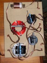
See attached pics of the prototype crossovers which have the footprint of A4 paper each.
-Dan
1 happy little vegemite.
The cross overs took me quite a long time to "knock up" they are
just zip tied to MDF at the moment I will probably put them in an enclosure much more neatly in the near future.
I ended up using:
Jaycar 9.0mH
Solen 1.0mH (measured 1.0003 mH@1kHz / 0.347 Ohms @ 100Hz)
Generic 1.8, 0.82 and 0.47 Inductors (all less than 0.5 Ohm DCR)
3.3uF Solen Polypropylene
10uF Solen Polypropylene
68uF Generic aluminium electrolytic (NP)
4.7uF Solen tin foil
10W MOX resistors 1-2% tolerance.
I measured all parts were correct prior to use.
I am really happy with the sound. highs are crystal clear, bass is very fast, clean and deep and they sound flat to 20Hz (in room) The bass/mid bass tones are really easy to differentiate there is no "boominess' or resonance which can sometimes be an issue with subwoofers designed more for SPL in a small user friendly package. I really like the speed and depth of the bass.
The tweeters (Peerless HDS) really are sweet, the highs are excellent, cymbal crashes are smooth, instrument picks are not lost, singers taking a breath etc etc i can hear things which were muddled in my other speakers i did not even know they were there.
Mids are also excellent they sound very natural... actually across the board they are hard to fault.
See attached pics of the prototype crossovers which have the footprint of A4 paper each.
-Dan
1 happy little vegemite.
Attachments
Hello Salas,
Thanks for the interesting link the info is useful.
The coils are placed approx 15cm apart.
I intend rebuild the crossover in a wooden box, with a neater layout.
Perhaps I will make it larger than first anticipated !!!!
one other thing, the rebuild will use solid core tinned copper wire and i think the caps will be "hot glued" or "siliconed" in place.
should be alot neater.
Despite the simplicity the crossovers are deceptively large !
-Dan
danieljw said:
Despite the simplicity the crossovers are deceptively large !
-Dan
Well done Dan. Nice description of your first impressions, can I quote you?
Re the choke layout, the one numbered "6" in that link, is the most useful as it allows the most compact crossover. Even then a little space should be there. But chokes that have relative axis at 90 degrees is a good thing. See "6" and "7" below.
Joe R.
Attachments
Hi just caught up with the tail end of this thread.
Is this project fully documented as a "free design"
with the current plans and crossover published,
or is it purchased from the designer for a fee?
Couldn't read thru the entire back to front yet.
Sounds like a great project with the added discount on drivers at Madisound.
Regards,
Ralph
USA
Is this project fully documented as a "free design"
with the current plans and crossover published,
or is it purchased from the designer for a fee?
Couldn't read thru the entire back to front yet.
Sounds like a great project with the added discount on drivers at Madisound.
Regards,
Ralph
USA
I could't edit my post so more question.
Could these be built in 2 seperate stacked boxes
like you can buy at Parts Express? I think their largest MTM
boxes are 1 CF ea.
This would mean venting the top and bottom cabs seperately
I suppose, but maybe you could join the two volumes with a large cutout ?
Could these be built in 2 seperate stacked boxes
like you can buy at Parts Express? I think their largest MTM
boxes are 1 CF ea.
This would mean venting the top and bottom cabs seperately
I suppose, but maybe you could join the two volumes with a large cutout ?
If you check out Joe's website, it pretty much documents 90% of the design of the speaker and yes, thanks to Joe's generosity, it is all free.
I would not go the ready made box path. If you change the box, you may as well the entire design and start all over from scratch. It is part and parcell of the whole shebang.
I would not go the ready made box path. If you change the box, you may as well the entire design and start all over from scratch. It is part and parcell of the whole shebang.
rob323 said:If you check out Joe's website, it pretty much documents 90% of the design of the speaker and yes, thanks to Joe's generosity, it is all free.
I would not go the ready made box path. If you change the box, you may as well the entire design and start all over from scratch. It is part and parcell of the whole shebang.
The other 10% is where?

In my head?
There is all that is required to build the design (see by-line link below), but those who have bought kits do also get a piece of me and all necessary attention to detail that may be of additional help.
Re the box, there are air flows to take into account and a round hole or a buch of smaller ones won't achieve the aim, that the vertical velocity at the rear of the box is slower than the front - there is a variable vertical resistive element and not the "lined box" normally used in ported/reflex alignments.
While the design is free, it is NOT public domain. You have an implied license to build one pair for personal non-profit use.
Joe R.
Joe Rasmussen said:
"those who have bought kits do also get a piece of me"
Joe R.
The piece is Joe's right arm.... or at least an equivalent amount of information
(bad joke)So much useful info listed.
Build a pair to spec you wont be disappointed.
-Dan
- Home
- Loudspeakers
- Multi-Way
- The "Elsinore Project" Thread