Really...? I thought that the different mediums would have have a different effect on the equivalent volume. Or does this not apply as the insulation is only used to line the sides of the cabinet?
keep the same thickness that's all.
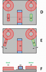
Thanks for that, I was thinking that myself but wasn't sure if it was needed. What about the spacing? Would I be able to bring it all a bit closer in as at the moment its an A4 paper size layout and would like to get it a little smaller if possible.
You can play with the coils placement, but it looks already good.
Maybe put the two corner bottom coils on their side.
Here's a nice article about coils placement.
Hi,
I have been trolling the polymax website, and it looks like their insulation batts are now 100% polyester not the wool blend as specified on Joe's website.
Try:
Abbco Insulation
26/55-59 Norman St
Peakhurst NSW 2210
(02) 9544 9043
Note they do bats that are 'acoustic' grade. Last time I got some, they were a mixture of polyester and wool.
Cheers, Joe
Thanks for that, I was thinking that myself but wasn't sure if it was needed. What about the spacing? Would I be able to bring it all a bit closer in as at the moment its an A4 paper size layout and would like to get it a little smaller if possible.
I doubt that you will be able to avoid crosstalk between coils in a A4 paper size layout. Why not use the available space behind the speakers like I did? 8" between coils should avoid any crosstalk. You can put them closer, but you will need to take care about how you place them in relationship to the other ones.
Attachments
Last edited:
I doubt that you will be able to avoid crosstalk between coils in a A4 paper size layout. Why not use the available space behind the speakers like I did? 8" between coils should avoid any crosstalk. You can put them closer, but you will need to take care about how you place them in relationship to the other ones.
Looks good, one question though: What happened to the BR Port? It looks like it's diameter is cut in half?
Looks good, one question though: What happened to the BR Port? It looks like it's diameter is cut in half?
That's an optical illusion. The BR ports are not obstructed (around 2 inches below the crossover frame)
I doubt that you will be able to avoid crosstalk between coils in a A4 paper size layout. Why not use the available space behind the speakers like I did? 8" between coils should avoid any crosstalk. You can put them closer, but you will need to take care about how you place them in relationship to the other ones.
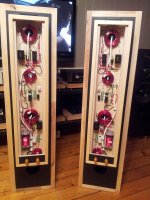
I do like the look and design but the problem i have with it is the wife factor she's already complaining about how big they are and if i add another 80 - 100mm well we all know that wont go down well, I can hide the external boxes under the TV Unit to keep the missus happy.
I've tried to find some info on how much the sound is affected by the cross talk but haven't found much, what is yours or anyone else's experience with it?
I've tried to find some info on how much the sound is affected by the cross talk but haven't found much, what is yours or anyone else's experience with it?
Look here in this thread for a discussion about coils layout in the crossover. You could use the layout of jdkJake, it's compact like you want and the layout minimize the interaction between coils,
http://www.diyaudio.com/forums/multi-way/97043-elsinore-project-thread-116.html#post3012890
Look here in this thread for a discussion about coils layout in the crossover. You could use the layout of jdkJake, it's compact like you want and the layout minimize the interaction between coils,
http://www.diyaudio.com/forums/multi-way/97043-elsinore-project-thread-116.html#post3012890
Thanks for that, i'll have a read.
OOPS - TYPO ERROR:
I have noted there was an error in the Crossover and L3 should have been 2mH (or 1.8mH) and not 3.9mH. What would have been the consequence of using the wrong value? Not hugely and in fact it comes down to the power handling of the Tweeter being not as good.
See updated Crossover below, only L3 has changed:
HI Joe
How is the crossover for the hamlet going? You mentioned a little while ago you would post up an updated version.
It has been a long trek, but the details will be posted some time during this week.
Cheers, Joe
I was wondering if there is anything wrong with using EREM soniQ inductors for the 20mH part.
Can you supply a link - tried to do a Google search. Keep in mind, horses for courses - using iron core in this instance may not be a problem, but I need to know more about the one you are considering.
Cheers, Joe
Sorry, my damn autocorrect failed me. It is the ERSE superQ, this one. ERSE - Super Q
Sorry, my damn autocorrect failed me. It is the ERSE superQ, this one. ERSE - Super Q
Ah yes, now it makes sense. But that inductor is not cheap and will it do the job without sacrificing anything performance wise? Absolutely OK.
I and others have used this 9mH from Jaycay/Electus and two gives you 18mH and price is somewhat more reasonable and in this instance would be just as good.
Note in the pic below it is the one on the right:
An externally hosted image should be here but it was not working when we last tested it.
Another and really excellent choice would be one of the Jantzen P-Coils available in 9mH and 10mH, better grade still and should be reasonably priced as well.
An externally hosted image should be here but it was not working when we last tested it.
I am sure there are other choices and they are all pretty equal in this particular task - this inductor largely form a current mirror seen by the amplifier rather than the driver, and for that reason, saturation is not likely to have as deleterious effect as if this was a series/filter inductor, and it is not. Also, the sensitivity nicely over 90dB/2.83V and the EL-6 are not power hungry and go loud easily - so again making inductor saturation much less of a problem - but it is not even used as a filter inductor anyway.
Hope that helps. I believe using money where it does the most good and that is in this order 1. 1.8uF series capacitor to the Tweeter. 2. 0.47mH for the series inductor to midrange and 3. 4mH (or 3.9mH) series inductor to the Bass.
In that order, C1, L2 and L3, get the best components money allows for.
Hope that helps.
Cheers, Joe
Hamlet Update:
The Crossovers are built - the boxes are being cleaned up as the got damaged during transit from Paul 'Spoonted' - at this stage I am thinking about listening to them on Saturday and checking that the Crossover behaves as per computer modelling. I have a fairly high expectation that it will be, as the modelling on the Elsinore 6's were spot on as well and the two were done at the same time and of course the similarity to EL-5 and this configuration is now well-tried and... it will work for sure.
It has been a long time coming and really relieved we are at this stage.
Cheers, Joe
.
On the subject of crossovers I would like to install them inside the boxes with a similar method posted by Joel Wessling Post #1192 without the binding post plate. But would put the mid/bass and tweeter crossovers on separate boards. Where would be the best location to mount these between the stiffening braces as not to affect the volume and dampening of the boxes? I was thinking close to top and back? Suggestions would be appreciated.
Thanx, TIm
Thanx, TIm
- Home
- Loudspeakers
- Multi-Way
- The "Elsinore Project" Thread