Crossover Mod
When I made the changes in the mid and bass circuits, my initial thought was that I lost bass response and upper mid range was more forward and hard sounding. But just last night I got a chance to listen at a decent volume without kids running around screaming in the background (my system is in our main living area, which is a big open room), and I noticed the bass was there and it was very clear with good transients. So now I'm at the skeptical point where I don't know if it is the new crossover parts breaking in or my ears are breaking in.
I've been trying Bolserst's mod for a couple weeks, now. I've got admit that I haven't mad up my mind, yet. One thing is for sure, adding the resistors across the terminals of each mid/bass drivers did make an improvement. I'm not sure of the best way to describe the difference - maybe more coherent?Has anyone else tried the Bolserst crossover mods besides Joel? Would be interested in your comments.
When I made the changes in the mid and bass circuits, my initial thought was that I lost bass response and upper mid range was more forward and hard sounding. But just last night I got a chance to listen at a decent volume without kids running around screaming in the background (my system is in our main living area, which is a big open room), and I noticed the bass was there and it was very clear with good transients. So now I'm at the skeptical point where I don't know if it is the new crossover parts breaking in or my ears are breaking in.
Thanks so much for the info and link Bolserst. It would seem that in an attempt to make a neat PCB that I completely overlooked the possibility of interaction. I did think about it briefly but discounted the effect thinking that the air cored inductors would have very sparse fields and wouldn't cross couple much. Obviously I was wrong on that one. I believe there is another more serious side effect of having inductors placed too close to each other. If the inductors are in different arms of the filter say MF and HF they would start to behave like a transformer causing cross modulation effects. I think this would be very detrimental to performance. As you can see from the photo I have made some mods to hopefully minimise all these effects using the existing pcb but I will now redo the artwork to completely remove any possibility of crosstalk and/or inductance change. What it does show up is that many commercial and quite expensive speakers break the rules completely.Hello irext,
Determining placement and orientation for minimum coupling between coils by ear:
Rules of thumb to minimize coupling basically boil down to 1) distance is good, 2) if you can’t get distance, proper axis orientation can help.
Here is another useful link on the subject with measurement:
Inductor Coil Crosstalk Basics — Reviews and News from Audioholics
For those without oscilloscopes or LCR meters, determining levels of goodness for these rules of thumb and any other arrangement can be done in a rather simple manner. Tools needed are a pair of headphones, amplifier, 4 ohm 20W resistor, and a signal generator or test disk. Hook the leads of one inductor to your headphones. Hook the leads of the second inductor to the amplifier with the 4 ohm resistor in series with one of the connecting wires. Play a 1kHz – 2kHz signal thru the amplifier. Usually < 10Watt is adequate to hear a strong tone in the headphones when the two coils are placed in close proximity to each other.
Listening to the amplitude of the tone, you can get a feel for how distance and orientation affects the coupling. You will find that at close distances minimizing the coupling thru axis orientation can be quite critical of angle adjustment.
Considerations for iron core inductors:
I noticed you had two 9mH iron core inductors hooked in series to get the required 18mH. However, when the iron cores of two inductors are positioned in-line and close together there is considerable mutual inductance generated thru coupling.
Attachment #1: Actual inductance measurements for two series connected 6mH inductors
(A) Where coupling is minimized by axis orientation, total inductance = 12mH
(B) Where mutual inductance is additive, total inductance = ~23mH
(C) Where mutual inductance is subtractive, total inductance = ~10mH
Case (B) can be used to your advantage when creating larger value inductors from two small ones. The gap between the cores can be adjusted to give a value anywhere between 2 to 4 times the individual inductances. For example, Attachment #2 shows an 18mH test inductor I build from the two 6mH inductors carefully spaced apart be MDF blocks.
So, depending on the orientation of your 9mH inductors I would estimate the total inductance is probably either ~23mH or ~16mH; not the 18mH you were going for. The good news is that this inductor is only used for impedance compensation "up-stream" of the woofer crossover and has fairly non-critical tuning. But, something to keep in mind if you ever use inductors like this for critical areas of a crossover.
Another thing to point out about case (C) is that the magnetic fields from the two inductors are bucking against each other. This results in a strong flux field shooting radially outward from the gap between the cores. So, positioning other inductors near this area is not a good idea. You can confirm this by listening to the tone from a coil placed in this area. Case (C) will produce considerable louder tones in the headphones than case (B). Attachment #3 is an attempt to graphically depict the behavior of the flux fields for cases (B) & (C).
Old tricks rediscovered:
While playing around with coil placement, you may accidentally stumble on the fact that there is another orientation besides orthogonal axes that will minimize coupling between coils. If you start with two coils spaced slightly apart and oriented in the same direction and then rotate both of them at the same time in the same direction, you will find somewhere in the 50deg – 60deg range the coupling completely disappears. The exact “magic” angle depends on the coil diameter and length, and is pretty easy to find by ear with the technique described above. This behavior was patented by Hazeltine (US 1577421) in the early 1920s for use in cascaded RF amplifiers in early unshielded radios. See Attachment 4 & 5. The cool thing is that you can line up any number of similar sized/shaped coils at the same spacing and angle and there will be minimal coupling between any/all of them.
What I notice about Joe Ras's passive crossover is that seems to rely on the overlap in frequency range on each arm of the crossover a fair amount (low order filters). The inductor in series with the midrange pair for instance is not there to roll off the pair per se but to shape the response. It would seem to me to be very difficult to reproduce this actively. What he seems to have done very cleverly is to choose well behaved drivers which require minimal crossover intervention thus mostly ist order filters and a very gentle approach, rather than lots of eq and high order networks, is required. My advise is to build the passive ones. I can vouch that they work very well.Thanks for that.
It looks like I will stay with the original passive crossover plan then.
Its a shame as I have two Rotel rb1080 power amps (was thinking of getting a third) but I can still bi-amp.
Maybe I'll even experiment with passive crossover for the mids and highs, and active for the mids and bass?
What are your thoughts?
My current crossover is a nakamichi ec100 two way with seperate power supply.
Coupling from coil to coil thru transformer action is exactly what the tone test I described up in post#1139 allows you to quantify and minimize. I agree that coupling from LF to HF driver crossovers is probably more detrimental than between coils within the same crossover. I tend to always build separate crossover boards for each driver and mount them as far away from each other as is practical...usually near cabinet brace points to minimize vibration. This was why I had suggested that tpate move his 18mH inductor as it was near the tweeter crossover and carries significant current.I believe there is another more serious side effect of having inductors placed too close to each other. If the inductors are in different arms of the filter say MF and HF they would start to behave like a transformer causing cross modulation effects. I think this would be very detrimental to performance.
I'm a bit puzzled by this result since the notch filter added to the mid/bass woofers removes a peak in the native response that tends to make female vocal sound forward or strident. So, adding the notch should alleviate this tendency not accentuate it. If your crossovers are external it is easy to quickly connect or disconnect the notch filter to hear the difference while playing pink noise. The difference will be most pronounced when listening on axis. Once you get more than about 25 degrees off axis, the difference becomes less noticeable.I've been trying Bolserst's mod for a couple weeks, now. I've got admit that I haven't mad up my mind, yet. One thing is for sure, adding the resistors across the terminals of each mid/bass drivers did make an improvement. I'm not sure of the best way to describe the difference - maybe more coherent?
When I made the changes in the mid and bass circuits, my initial thought was that I lost bass response and upper mid range was more forward and hard sounding.
Initial layout of the crossovers...
I was originally going to build and mount the crossovers in a fancy external case that matched the cabinets. However, I decided against it as I have a feeling I might tweak the layouts and components a bit going forward.
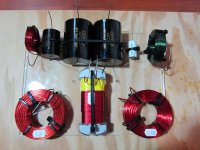
So, while my ugly-*** NEMA enclosure is in the paint chamber, I took a crack at an initial layout of the crossover components. I still have to place another 33uf cap and add the resistors, but, this looks to be my initial layout. The large horizontal air cores are 20cm apart and the rest have been oriented to minimize interaction between the inductors. The base they are mounted on is approximately 8inches by 11inches.
Comments are welcome. I will probably not get a chance to work on them anymore until the weekend.
I was originally going to build and mount the crossovers in a fancy external case that matched the cabinets. However, I decided against it as I have a feeling I might tweak the layouts and components a bit going forward.
So, while my ugly-*** NEMA enclosure is in the paint chamber, I took a crack at an initial layout of the crossover components. I still have to place another 33uf cap and add the resistors, but, this looks to be my initial layout. The large horizontal air cores are 20cm apart and the rest have been oriented to minimize interaction between the inductors. The base they are mounted on is approximately 8inches by 11inches.
Comments are welcome. I will probably not get a chance to work on them anymore until the weekend.
Attachments
I took a crack at an initial layout of the crossover components. I still have to place another 33uf cap and add the resistors, but, this looks to be my initial layout. The large horizontal air cores are 20cm apart and the rest have been oriented to minimize interaction between the inductors.
Comments are welcome.
Based on your allotted space and needing to fit that 18mH iron core inductor in amongst the air cores, I think your layout is pretty good. In particular L1, L3 & L4 probably couldn’t be placed any better. There may be some better options for L2 & L5.
Layout (A) – your initial layout
- minimal coupling between L1 & L5, and L2 & L3
- considerable coupling between L4 & L5, and L4 & L2
Layout (B) – alternate option 1
- some coupling between L1 & L5, and L2 & L3
- minimal coupling between L4 & L5, and L4 & L2
Layout (C) – alternate option 2
- coupling between L1 & L5, and L2 & L3; more than (A), but less than(B)
- minimal coupling between L4 & L5, and L4 & L2; critical angle alignment needed
If you tone test your initial layout for coupling between coils you will find L4 coupling considerable energy into L2 & L5. Positioning them flat as in (B) will minimize this coupling with L4, but coupling with the larger air coils L1 & L3 will have increased considerably. If instead L2 and L5 are rotated to angles similar to those shown in (C), coupling with L4 can be minimized, and coupling with L1 & L3 will be less than in (B). The only issue is that the angles will need to be determined by tone testing to find the null as they will depend on exact location and core dimensions/properties of L4.
Attachments
Thank you for the feedback bolserst. Very much appreciated.
Now that I look at my initial layout with the value of a second set of eyes, I do see how the layout exhibits the problematic symptoms outlined by Troels in his diagram #5.
Looks like I have a bit more work ahead of me. Option B is of course, very attractive due to the elimination of finding the critical angle. Although, I have access to the proper test equipment. The case I am using has some overlap room (overlap of the bottom plate shown in the pictures). I might be able to get the core centers of L1, L2, L3 and L5 closer to 20cm in separation in all directions by pushing them out.
Either way, I will have to experiment a bit. Thanks again for the feedback.
I will be very interested in your final layout as it may form the basis for a new PCB design. I fitted my original PCB into a large die cast box which I had planned to get powder coated. Trouble is once you start listening to your Elsinore,s it,s very hard to have them out of service while you make modifications.
I anticipated that being a problem, so I am painting my boxes first. :-D
This is the box I am using:
http://www.budind.com/pdf/hb1343.pdf
The box itself is molded, dark grey, high-impact ABS (Acrylonitrile butadiene styrene).
As it stands now, the .220 thick Lexan sheets I am using to mount the components upon fit inside the 8 x 10.8 inch boundary that goes up to the screw posts. There is a little less than an inch of extra space to the actual side of the box that might be exploited to get the centers of the air cores a bit farther apart. I really cannot play with it too much until the covers come out of paint. So far, they have taken about 8 light coats of spray to get the finish I want. I had to roughen with 120/220/320 grit to ensure the surface would accept the paint properly for a matte finish. One or two more coats ought to do.
I've found the Elsinore project so interresting that i've just ordered two HDS-164NOMEX ") .
.
I will evaluate this speaker in my current configuration Atohm D300P04 + Davis 16GKLV6M + Audax TW034.
http://www.diyaudio.com/forums/multi-way/23208-system-pictures-description-212.html#post2881608
Maybe in few month I will own these BIG towers
. I will evaluate this speaker in my current configuration Atohm D300P04 + Davis 16GKLV6M + Audax TW034.
http://www.diyaudio.com/forums/multi-way/23208-system-pictures-description-212.html#post2881608
Maybe in few month I will own these BIG towers
Wow, what a revelation!
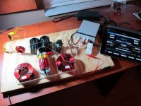
So I went ahead and hooked up the audio-based test setup that bolserst recommended. I figured that would be most reflective of what most people could cobble together without any issue. I sent the output of my iPad into a small T-amp I own, that output into the resistive load and into the inductor to stimulate. I attached my old sony test phones to the inductor under test.
All I can say is WOW!!!
This was a truly eye-opening experiment that I highly recommend folks try. It was extremely easy to set up and really lets you experience inductor coupling first hand. You really do not need any fancy test tones either. Simple music out of an iPod works just fine. Perhaps even better as the test tones get a bit tiring to listen too.
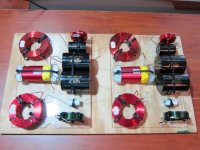
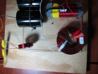
In any case, there is most certainly a critical angle for each inductor pairing. On the attached picks, the second pic shows the best angle to minimize L4 coupling. The third shows the angle that minimized L1/L3 coupling. Neither angle works perfectly for both inductors.
The correct placement of the inductors instantly becomes a game of compromise. I can see now why bolserst builds separate clusters for each driver and mounts them physically separate. There is really no other solution save for distance. We are not talking about small amounts of distance either, we are talking large amounts unless critical angles can be exploited. In my layout, even with critical angles being exploited, there is coupling of some level between all of the inductors. You really have to decide what you want to try to minimize and why.
So, now I am at sort of a crossroads. I will definitely go with inductor layout B that bolserst recommends. Long term, once I have decided the values for the crossover are acceptable, it will be mighty tempting to make the crossovers individual clusters for each set of drivers and mount them internally at the maximum distance possible.
In the meantime, I highly, highly recommend you give the bolserst test a go. It will blow your mind and teach you more about inductor layout than you could learn from a thousand books.
Thank you so much bolserst! I really cannot thank you enough. A learning day is a good day and today was a VERY good day.
So I went ahead and hooked up the audio-based test setup that bolserst recommended. I figured that would be most reflective of what most people could cobble together without any issue. I sent the output of my iPad into a small T-amp I own, that output into the resistive load and into the inductor to stimulate. I attached my old sony test phones to the inductor under test.
All I can say is WOW!!!
This was a truly eye-opening experiment that I highly recommend folks try. It was extremely easy to set up and really lets you experience inductor coupling first hand. You really do not need any fancy test tones either. Simple music out of an iPod works just fine. Perhaps even better as the test tones get a bit tiring to listen too.
In any case, there is most certainly a critical angle for each inductor pairing. On the attached picks, the second pic shows the best angle to minimize L4 coupling. The third shows the angle that minimized L1/L3 coupling. Neither angle works perfectly for both inductors.
The correct placement of the inductors instantly becomes a game of compromise. I can see now why bolserst builds separate clusters for each driver and mounts them physically separate. There is really no other solution save for distance. We are not talking about small amounts of distance either, we are talking large amounts unless critical angles can be exploited. In my layout, even with critical angles being exploited, there is coupling of some level between all of the inductors. You really have to decide what you want to try to minimize and why.
So, now I am at sort of a crossroads. I will definitely go with inductor layout B that bolserst recommends. Long term, once I have decided the values for the crossover are acceptable, it will be mighty tempting to make the crossovers individual clusters for each set of drivers and mount them internally at the maximum distance possible.
In the meantime, I highly, highly recommend you give the bolserst test a go. It will blow your mind and teach you more about inductor layout than you could learn from a thousand books.
Thank you so much bolserst! I really cannot thank you enough. A learning day is a good day and today was a VERY good day.
Attachments
This was far more fun!
I actually had an o-scope and signal generator ready to go. That combo or an LCR meter would probably be a better choice for optimizing between multiple inductors as relative levels could be compared far more easily.
Still, it was a hoot listening to tunes travel across inductors.
I actually had an o-scope and signal generator ready to go. That combo or an LCR meter would probably be a better choice for optimizing between multiple inductors as relative levels could be compared far more easily.
Still, it was a hoot listening to tunes travel across inductors.
I actually had an o-scope and signal generator ready to go. That combo or an LCR meter would probably be a better choice for optimizing between multiple inductors as relative levels could be compared far more easily.
Still, it was a hoot listening to tunes travel across inductors.
Hello jdkJake,
Congrats on the good learning day!

It is pretty cool that you can get a handle on magnitude of coupling between coils without any special test equipment.
In fact, I personally find it quicker & easier to determine critical angles to minimize coupling with this test than with an LCR meter.
Yeah, music may be easier on the ears than test tones for extended test sessions
But, it may be easier to compare different configurations if constant amplitude test tones are used.
Obviously an O-scope would make this even easier, but not everybody has access to one.
I did think of two other coil layouts you might consider which should allow minimizing coupling between more coils simultaneously. Both involve moving L1 & L3 to the opposite side of the board. Since this will move them into an area of higher flux density from L4, it will be more important to make sure the midpoint of the height of the coils match the midpoint of core of L4. See Figure (F) in attachment for details.
Layout (D) has L2 & L5 oriented vertically and placed on the centerlines of L3 & L1 respectively, thus minimizing coupling. L2 & L5 are also placed parallel to the core of L4 and at the midpoint of the length of the core. This minimizing coupling with L4.
Layout (E) also has L2 & L5 oriented vertically and placed on the centerlines of L3 & L1 respectively. But unlike (D), the coils L2 & L5 are placed as close as possible to L3 & L1. Then their angle of orientation is adjusted by sliding them around L3 & L1 to a point that minimizes coupling between L2 & L5 and L4. Coupling with L3 & L1 will still be minimal since the coils stay on a centerline with L3 & L1.
Attachments
I've been reading these posts with great interest. I think I might buy another complete set of inductors so I can do some testing without ripping my Xovers apart. Fortunately I have access to an oscilloscope an LCR bridge and a signal generator. It will be interesting to see the relationship between cross coupling and inductance change. Since building my xovers I've found a source of 18mh inductors which would be nicer than using the two 9mh in series. It will make the layout a lot easier. After the repositioning of the inductors on my existing PCB, without actually doing any signal measurements, a noticeable improvement is evident, particularly at higher listening levels. It's nice when you can improve on something that already performs extremely well. I'm also very interested to hear a listening review from JK. You must be so close to firing up those lovely looking Elsinore's!
Last edited:
I've been reading these posts with great interest. I think I might buy another complete set of inductors so I can do some testing without ripping my Xovers apart. Fortunately I have access to an oscilloscope an LCR bridge and a signal generator. It will be interesting to see the relationship between cross coupling and inductance change. Since building my xovers I've found a source of 18mh inductors which would be nicer than using the two 9mh in series. It will make the layout a lot easier. After the repositioning of the inductors on my existing PCB, without actually doing any signal measurements, a noticeable improvement is evident, particularly at higher listening levels. It's nice when you can improve on something that already performs extremely well. I'm also very interested to hear a listening review from JK. You must be so close to firing up those lovely looking Elsinore's!
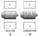
The power lost in the form of heat in the armature winding of a generator is known as COPPER LOSS. Heat is generated any time current flows in a conductor. Copper loss is an I2R loss, which increases as current increases. The amount of heat generated is also proportional to the resistance of the conductor. The resistance of the conductor varies directly with its length and inversely with its cross- sectional area. Copper loss is minimized in armature windings by using large diameter wire. What causes copper losses? Eddy Current Losses The core of a generator armature is made from soft iron, which is a conducting material with desirable magnetic characteristics. Any conductor will have currents induced in it when it is rotated in a magnetic field. These currents that are induced in the generator armature core are called EDDY CURRENTS. The power dissipated in the form of heat, as a result of the eddy currents, is considered a loss. Eddy currents, just like any other electrical currents, are affected by the resistance of the material in which the currents flow. The resistance of any material is inversely proportional to its cross-sectional area. View A, shows the eddy currents induced in an armature core that is a solid piece of soft iron. View B, shows a soft iron core of the same size, but made up of several small pieces insulated from each other. This process is called lamination. The currents in each piece of the laminated core are considerably less than in the solid core because the resistance of the pieces is much higher. (Resistance is inversely proportional to cross-sectional area.) The currents in the individual pieces of the laminated core are so small that the sum of the individual currents is much less than the total of eddy currents in the solid iron core.
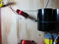
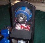
I started thinking about this when I discovered that the 9mh erse that came out of MkIV has laminated iron core and the cheap 18mh in MKV is Solid.
Also the Erse is made much better and wound evenly. The core on the cheapy slided out and windings waver around the spool...
I'm sticking with the better made 9's unless I can find same quality in 18mh
Regards, Joel
Attachments
What it does show up is that many commercial and quite expensive speakers break the rules completely.
Not exactly Elsinore related, but stumbled on this pic showing the crossover coil layout for the GR Research Super V.
Looks to have had some thought/experimentation put into it.
Attachments
bolserst,
Thanks for taking the time to diagram the additional inductor layouts. They are certainly worth exploring. Layout E is especially intriguing. At this point, as of last weekend, I started to build up layout B. That will be my starting point for going forward.
irext,
I am close, but still a bit further out from firing them up. Unfortunately, I ran out of the wire I was using for the point-to-point wiring of the cross over. I should have more available by the weekend to finish the job. Measure twice right? I look forward to your inductor experiments.*
Joel,
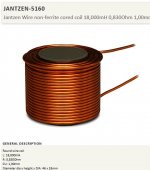
I am using a Erse Super-Q, 16AWG, laminated 18mH steel core. You can get them directly from Erse (ERSE - Super Q). I ordered all my inductors and all the film caps save for C1 directly from them. Be advised, even if they indicate something is out of stock, it usually isn't (or at least not out for long). BTW, Jantzen makes a big ole toroidal air core in that size. (Jantzen 18mH 14 AWG C-Coil Toroidal Inductor 255-844). Far from cheap though!
Thanks for taking the time to diagram the additional inductor layouts. They are certainly worth exploring. Layout E is especially intriguing. At this point, as of last weekend, I started to build up layout B. That will be my starting point for going forward.
irext,
I am close, but still a bit further out from firing them up. Unfortunately, I ran out of the wire I was using for the point-to-point wiring of the cross over. I should have more available by the weekend to finish the job. Measure twice right? I look forward to your inductor experiments.*
Joel,
I am using a Erse Super-Q, 16AWG, laminated 18mH steel core. You can get them directly from Erse (ERSE - Super Q). I ordered all my inductors and all the film caps save for C1 directly from them. Be advised, even if they indicate something is out of stock, it usually isn't (or at least not out for long). BTW, Jantzen makes a big ole toroidal air core in that size. (Jantzen 18mH 14 AWG C-Coil Toroidal Inductor 255-844). Far from cheap though!
- Home
- Loudspeakers
- Multi-Way
- The "Elsinore Project" Thread