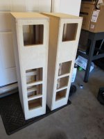
"Inner Cabinet" assembly
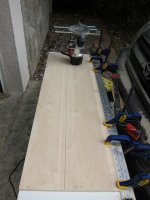
Another day, another day with the router, bowclamps and glue.
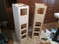
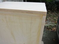
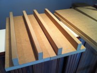
Made the same grooves as with the back panel (I mis-stated previously as dados are perpendicular to the grain vice grooves which are parallel to the grain). The first cabinet went together smooth as silk! One could not ask for better. Which, meant the second one would, of course, provide much heart-ache (Note, the "slightly bowed" comment above referred to one of the center braces). In any case, after much thought and the application of many clamps and home-made cauls to straighten the center brace, a second cabinet finally emerged.
In any case. still making progress. I even went Titebond III to get a few extra minutes of working time. Probably unnecessary in the end as the grooves make it so much easier. I left a few millimeters on each side that I will remove with a flush-trim bit. Did I mention how much I LOVE my router!
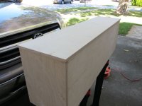
Finally starting to look like something plausible....
Another day, another day with the router, bowclamps and glue.
Made the same grooves as with the back panel (I mis-stated previously as dados are perpendicular to the grain vice grooves which are parallel to the grain). The first cabinet went together smooth as silk! One could not ask for better. Which, meant the second one would, of course, provide much heart-ache (Note, the "slightly bowed" comment above referred to one of the center braces). In any case, after much thought and the application of many clamps and home-made cauls to straighten the center brace, a second cabinet finally emerged.
In any case. still making progress. I even went Titebond III to get a few extra minutes of working time. Probably unnecessary in the end as the grooves make it so much easier. I left a few millimeters on each side that I will remove with a flush-trim bit. Did I mention how much I LOVE my router!
Finally starting to look like something plausible....
Attachments
Adding the tweeter stiffening panel and routing the excess
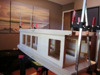
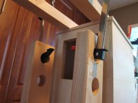
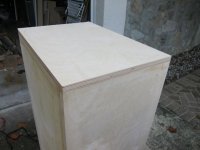
Still had a bit more time before returning back to work and the obligations of the real world. Constructed and installed the tweeter stiffening panels.
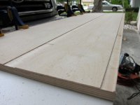
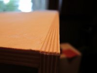
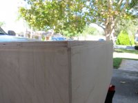
Also took a flush trim bit to trim the excess I left when I formed the assembly grooves. Boy, did that work well. Really turned out far better than I could have hoped for; a clean assembly and a clean finish.
Still had a bit more time before returning back to work and the obligations of the real world. Constructed and installed the tweeter stiffening panels.
Also took a flush trim bit to trim the excess I left when I formed the assembly grooves. Boy, did that work well. Really turned out far better than I could have hoped for; a clean assembly and a clean finish.
Attachments
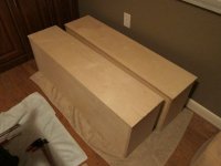
So, how did we do?
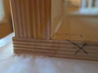
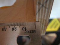
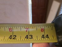
Now that the cabinets are together, time to check up on how close I got with the overall cabinet measurements.
This is my first cabinet build, so, lot's and lot's of learning and rookie mistakes, even when measuring twice (or what seemed like six hundred times for that matter).
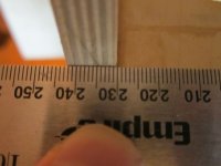
Width is fine, even better than expected. As for length, well, I am shy by about 5mm overall on length. Ouch. I knew I might have took a bit too much on the final straightening runs. Oh well, it is what it is and not too shabby considering 14 boards were length-sized identically. At least they are all straight, parallel and perpendicular on all angles.
Time to move on to constructing the outer box (famous last words, right?). I suspect this will go far quicker as the router can seemingly resolve a multitude of sins. Both real and imagined.
Did I ever mention how much I love my router?
Now that the cabinets are together, time to check up on how close I got with the overall cabinet measurements.
This is my first cabinet build, so, lot's and lot's of learning and rookie mistakes, even when measuring twice (or what seemed like six hundred times for that matter
).Width is fine, even better than expected. As for length, well, I am shy by about 5mm overall on length. Ouch. I knew I might have took a bit too much on the final straightening runs. Oh well, it is what it is and not too shabby considering 14 boards were length-sized identically. At least they are all straight, parallel and perpendicular on all angles.
Time to move on to constructing the outer box (famous last words, right?). I suspect this will go far quicker as the router can seemingly resolve a multitude of sins. Both real and imagined.
Did I ever mention how much I love my router?
Attachments
jdkJake, Looks like the build is going nicely. I don't understand your comment about building the outer box. If you add width and height to the cabinet it will change the sound of the finished product. Different diffraction because of different distances to edges. Or are you going to veneer over the end grains?
jdkJake, Looks like the build is going nicely. I don't understand your comment about building the outer box. If you add width and height to the cabinet it will change the sound of the finished product. Different diffraction because of different distances to edges. Or are you going to veneer over the end grains?
So, in actuality, I am not changing the overall dimensions of the cabinet, just in how those dimensions are applied.
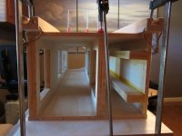
Since I am using 12mm ply, I need to double up on the layers to reach the desired thickness and overall cabinet dimensions. For the internal brace, back braces and sub-front panel, I have already done this and installed doubled up pieces. If you notice, I have not done that with any of the current outer walls of the cabinet, they remain at 12mm and still need to be doubled up in order to reach the final desired dimensions.
This is where I attempt to get clever
. I figured since I need to double up on the 12mm ply, I may as well do it in layers such that the second layer can overlap the seams of the inner layer. My rationale is that this would greatly aid in making the cabinet air tight as well as increasing overall strength. The real beauty is that the outer layers can be applied using roughed-in dimensions, glued and trimmed to exact fit with my beloved router. Yes, I apparently need professional help for what is starting to become an unhealthy fascination with my router.Anyway, that is the plan. I am committed at this point, so, we shall see how it goes. In theory, the final product will reflect Joe's design as intended (save for being short by ~5mm, Grrrr!).
So, in actuality, I am not changing the overall dimensions of the cabinet, just in how those dimensions are applied.
Since I am using 12mm ply, I need to double up on the layers to reach the desired thickness and overall cabinet dimensions. For the internal brace, back braces and sub-front panel, I have already done this and installed doubled up pieces. If you notice, I have not done that with any of the current outer walls of the cabinet, they remain at 12mm and still need to be doubled up in order to reach the final desired dimensions.
This is where I attempt to get clever
Anyway, that is the plan. I am committed at this point, so, we shall see how it goes. In theory, the final product will reflect Joe's design as intended (save for being short by ~5mm, Grrrr!).
Did you say you are going to install side panels after you get the final 24mm or miter the last panels togther to hide end grain?
Got it. Very ambitious. The front board is going to be 3/4 inch thick to match the wave guide thickness and set the offset for the tweeter?
Yup. I am going to cheat a bit there and use a piece of 1/4 inch MDF glued to a 12mm piece of ply to get the final thickness. The MDF piece will be between the sub-front panel and the actual front panel.
Did you say you are going to install side panels after you get the final 24mm or miter the last panels togther to hide end grain?
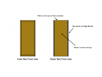
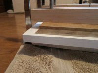
No, the side panels will bring the final thickness to 24mm. They will be edge-banded. I will miter the top/front transition (to hide the end grain) and extend the front panel to cover the bottom cap completely.
A picture (below) is hopefully worth a thousand words.
Attachments
No, the side panels will bring the final thickness to 24mm. They will be edge-banded. I will miter the top/front transition (to hide the end grain) and extend the front panel to cover the bottom cap completely.
A picture (below) is hopefully worth a thousand words.
Now I remember. I guess you could get creative with the edge-banding
It's weird but a router is a cool tool
I am going to give the edge banding a go. I have a friend who builds furniture grade cabinets and he has not experienced the issues you have seen with grain bleed-through. True, he has not used BB ply, but, he has used cheaper grades of ply without issue. Perhaps the thickness and glue used with iron-on edge banding is the difference, perhaps not. Guess we will find out.
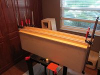
Capping the top and bottom
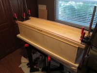
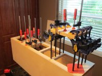
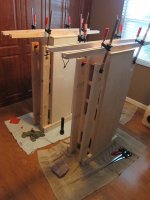
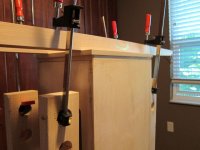
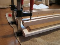
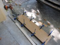
I wasn't completely sure how I was gonna pull this one off. I really did not want to spend the cash on 48inch pipe clamps mainly because I was not completely sure where I would store them once finished (my garage is already brimming with stuff) or if I would ever use them again.
Surfed the net a bit and got pieces of the idea for the fixture pictured below. Five scrap two-by-fours and a few 3/8inch carriage bolts and I was in business. Worked great and allowed my to reuse my 12inch clamps.
Initial layer of cap material is applied.
Attachments
Adding a layer of material to the backs
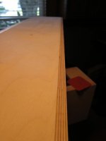
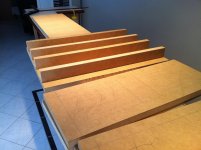
So far, the overlay technique is working out well. I am just rough cutting the material and then flush trimming the final piece after glue up. This works really fast. Much faster than the precision cuts required to make the interior pieces identical. Covers the underlying seams nicely.
The pics are the backs being thickened to the full inch of material. Also broke out the fixture to clamp another layer on for the bottom.
Big problem now is that they are starting to get heavy!
Oh well, just need the front and top panels as well as the final sides to complete the cabinets. My veneer showed up today, so, that will be a completely new adventure as well. Can't wait.
Attachments
Error on New Front Panel Drawing
Joe,
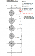
I found an error on the revised front panel drawing. The distance from the top of the panel to the mid-point of the top mounting hole should be 118mm vice the 114mm as shown (see attached annotated drawing). As currently specified, the alignment of the front panel is off by 4mm the entire distance of the front panel with regard to the sub-front panel.
Please correct soonest.
Thanks.
Joe,
I found an error on the revised front panel drawing. The distance from the top of the panel to the mid-point of the top mounting hole should be 118mm vice the 114mm as shown (see attached annotated drawing). As currently specified, the alignment of the front panel is off by 4mm the entire distance of the front panel with regard to the sub-front panel.
Please correct soonest.
Thanks.
Attachments
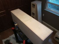
Additional layer on the bottom panel
Trimmed up the additional layer on the bottom. The overlapping seams work well. In the end, those side seams will be completely covered by the final side panels, so, you will not see any of those joints.
Trimmed up the additional layer on the bottom. The overlapping seams work well. In the end, those side seams will be completely covered by the final side panels, so, you will not see any of those joints.
Attachments
Constructing the layered front panel
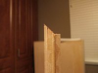
Cut and mitered the front panel using a champher bit. I had a steel bit on hand, but, in hind sight, I should have gone and bought a carbide. The steel bit struggled and scorched the wood a bit. Nothing too bad, but, the process could have gone better (mostly smoother). I also constructed the additional 1/4inch MDF cheater panel needed to bring the total thickness to 3/4inch.
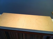
Measured out the centers for the holes and glued up the pieces to build up the composite front panel. Yes, they are slightly oversized to support the flush trim technique that has worked so well (thus far anyway).
Bring on the Jasper Jig....
Cut and mitered the front panel using a champher bit. I had a steel bit on hand, but, in hind sight, I should have gone and bought a carbide. The steel bit struggled and scorched the wood a bit. Nothing too bad, but, the process could have gone better (mostly smoother). I also constructed the additional 1/4inch MDF cheater panel needed to bring the total thickness to 3/4inch.
Measured out the centers for the holes and glued up the pieces to build up the composite front panel. Yes, they are slightly oversized to support the flush trim technique that has worked so well (thus far anyway).
Bring on the Jasper Jig....
Attachments
Hamlets
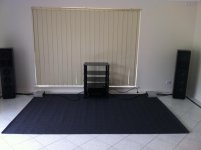
Hi all started on the hamlets today so i took a couple photos,also added one of my new stereo room which needs some more furniture/rugs etc.
Any body remember the size of the port, i had a look threw the entire post a while back and i,m pretty sure it was never decided upon.
Any suggestion ideas wishes to the placement of port/wiring terminals etc
I made the front panel larger so there will be no visible joins etc,reduced the other panels by 18mm to suit.
Attachments
I made the front panel larger so there will be no visible joins etc,reduced the other panels by 18mm to suit.
Looking good. Does this mean you are using 18mm material vice 24mm material?
I could not find any final value for the port size either. I do not believe it was ever calculated.
A dedicated listening room huh? Nice. Wish I had the room for a decanted space.
Looking good. Does this mean you are using 18mm material vice 24mm material?
A dedicated listening room huh? Nice. Wish I had the room for a decanted space.
Its still the same as the elsinores 24mm just changed the front panel dimension (ie increased its size so it goes to the edge and can be flush trimmed asi think you have done ) to suit the mk5 waveguide and give a cleaner look.
Same as you have done but i will just glue and screw down no rebate.
I,ll keep it simple without special tools etc as per Joes original idea.
Cutting List
25mm MDF
616 x 230 x 6 back panel/brace /sub panel
616 x 50 x 4 back braces
616 x 362 x 4 top/bottom
362 x 280 x 4 sides
230 x 200 x 2 tweeter stiffening
18mm MDF 666 x 280 x 2 Front panel
(You can add extra couple of mm to flush trim.)
 Edited per request of member
- Home
- Loudspeakers
- Multi-Way
- The "Elsinore Project" Thread