Joe Rasmussen said:
"those who have bought kits do also get a piece of me"
Joe R.
I guess this is testament to how much useful info Joe has listed
I for one appreciate his efforts.
")
Build a pair to spec you wont be disappointed.
-Dan
danieljw said:
Build a pair to spec you wont be disappointed.
-Dan
I can honestly say, as far as I am aware off, anyone who has built them, no-one has regretted it. I agree that there is always a bit of faith involved before one embarks on what is a considerable project, so the assurance of others who have taken the road, is invaluable.
But, and I want to say this with some fervour, not everything is related to money (I heard a quote that it was the "American Decease") and success is as much to do with accomplishment and satisfaction. Real success is also measured in the eyes of others and on the basis of what you contribute, and not by the size of your pay packet.
Joe R.
Thanks for input as buying 4 boxes from PE might be more expensive anyway plus I love sawdust in the morning.
I can get free plywood from work as we have 1" high density plywood used for concrete forms. Many odd pieces get thrown out and recyling is a good thing. Would plywood be acceptable?
Is the crossover for the current drivers on Joe's website or buried in this thread?
I am about to place Madisound order.
Thanks
Ralph
Ralph Johnsen said:
Would plywood be acceptable?
Is the crossover for the current drivers on Joe's website or buried in this thread?
I am about to place Madisound order.
Thanks
Ralph
Others have used good grade plywood and the results have been more than acceptable.
Re the crossover, not at all buried but is about two-thirds down the first page (that has links to other pages), right here:
customanalogue.com/elsinore/elsinore_index.htm
Construction Drawings:
customanalogue.com/elsinore/elsinore_4.htm
Internal Wiring and Damping:
customanalogue.com/elsinore/elsinore_5.htm
Useful construction photos - note some relate to Mark 1, but still are useful IMO:
customanalogue.com/elsinore/elsinore_6.htm
IF you are interested in the inner theory of the crossover:
customanalogue.com/elsinore/elsinore_17.htm
Why is that Tweeter in THAT phase? Read the article "Renegade Tweeter Theory":
customanalogue.com/elsinore/elsinore_19.htm
Finally, the FAQ page:
customanalogue.com/elsinore/elsinore_11.htm
From a constructor's point of view, those are the highlights.
Joe R.
Are there different drawings for the tweeter waveguide as they apply to the HDS tweet or do the original drwings still get used?
Looks like you start with several layers of mdf and then make waveguide from built up felt, do you use autobody filler or something similar to make a smoothed waveguide surface first?
Looks like you start with several layers of mdf and then make waveguide from built up felt, do you use autobody filler or something similar to make a smoothed waveguide surface first?
Ralph Johnsen said:Are there different drawings for the tweeter waveguide as they apply to the HDS tweet or do the original drwings still get used?
Looks like you start with several layers of mdf and then make waveguide from built up felt, do you use autobody filler or something similar to make a smoothed waveguide surface first?
The current box construction drawings are definitely Mk3 (using HDS tweeter).
Some of the photos show Mk1 and Mk2. As it says clearly "The Photos below relate to older Mark 1 and Mark 2 versions".
Ignore the four-sided waveguide shown in these photos and use the Felt pieces instead, as shown at the bottom of customanalogue.com/elsinore/elsinore_4.htm.
The two Felt pieces simply sits inside the cavity that the tweeter is mounted - the tweeter needs to be flush mounted inside that acivity, so that the inner Felt piece fits flat, as shown at the bottom of customanalogue.com/elsinore/elsinore_index.htm.
Joe R.
OK don't mean to be thick, just ordered my drivers and will start cabs soon.
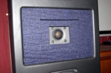
I copied the attached picture from a completed elsinore someone posted.
Is this the setup for the HDS tweet ?
Would it be better to have smooth transition rather than a couple of steps ? Would be easy to smooth out.
I copied the attached picture from a completed elsinore someone posted.
Is this the setup for the HDS tweet ?
Would it be better to have smooth transition rather than a couple of steps ? Would be easy to smooth out.
Attachments
Ralph Johnsen said:
Is this the setup for the HDS tweet ?
Would it be better to have smooth transition rather than a couple of steps ? Would be easy to smooth out.
Yes, that is it. The felt used as shown in that pic came from me, to Rob (rob323 is Rob a Mazda guy?). Others who have done their own and could not get the same thickness of felt - around 8-9mm (although the manufacturer says it's supposed to be 6.3mm or somesuch). They have used three layers, even seen a four layer. But as you say, if it smooths it out a bit it will not likely be a problem. But avoid making the cutouts in the felt round, keep them square as show, just more layers with cutouts spread out. I don't think that will cause anything adverse. BTW, round cutouts tend to show up at the same frequency, square spreads it out, generally speaking.
Good news, sounds like you are on your way. Go for it!
Joe R.
Just a quick question before I start making sawdust.
Could the lower 2 woofers be changed to the Peerless Nomex 8" woofers to offer a little more extension and ultimate bass capability?
The extra cost is fairly small
I realize the box will need to be larger maybe just extend the front to back dimension?
http://www.tymphany.com/datasheet/printview.php?id=13
Ralph
Ralph Johnsen said:Just a quick question before I start making sawdust.
Could the lower 2 woofers be changed to the Peerless Nomex 8" woofers to offer a little more extension and ultimate bass capability?
The extra cost is fairly small
I realize the box will need to be larger maybe just extend the front to back dimension?
http://www.tymphany.com/datasheet/printview.php?id=13
Ralph
I sat upon the basic idea on the specific idea that the Elsinores are based upon for a number of year. It was to reduce thermal build-up in the voice coil by a theoretical sixteen to one.
It goes like this:
Scenario: Theoretical Driver 8 Ohm 90 dB Sensitivity
Voltage Amplifier (very low output impedance), 2.83V RMS out that does not change with load impedance.
2.83V RMS into 8 Ohm driver = 1 Watt
A microphone at 1 Metre will confirm 90dB SPL - no surprise.
Question: What happens within the voice coil of that driver? It basically has to dissipate the heat, 1W of heat within 1%.
Next Scenario: We now get an extra identical driver and parallel that with our existing driver, note identical. The sum impedance will now be 4 Ohm, the RMS current drawn at 2.83V RMS will double, hence the amplifier will now supply 2 Watt.
Question: What will the microphone now see: Answer is 96dB SPL.
This requires some analysis. It is clear that each of the two voice coils are now dissipating 1 Watt each. It is also clear that we have 6dB more output. This means we are getting 3dB from the doubling of the power and 3 dB from increased efficiency. Note that sensivity and efficiency is not the same but often confused as being the same. This is a case case that proves the point.
This extra 3dB for FREE is gained by the drivers 'seeing' each other on the same front baffle and stiffening the air, so the push becomes more effective, more efficient really. It comes down to modifying the 'air load.'
Scenario # 3: What would happen if instead of paralling the drivers we connect them in series? Now the collective amplifier load would become 16 Ohm (the air load remains the same) and relative to our first scenario, it will halve the current drawn from the amplifier = 1/2 Watt. We now only have half the heat to dissipate. But...
Now what would be our dB SPL be at 1 metre now. Would you believe the same as a sigle driver. 90db SPL.
Are you seeing where this going? We now have no increase in sensitivity, but have DOUBLED our efficiency!!!
Now for the clincher.
Scenario # 4: What if we leave our series pair as in #3 still connected and add another series pair across amplifier terminals?
Again some analysis: It is clear we now are back to 8 Ohm and thus drawing 1 Watt as we was with our single driver in our first scenario.
But what will our 1 Metre dB SPL now look like?
96dB SPL !!!
I wonder if the point is clear. We have gained 6dB in pure EFFICIENCY.
Further analysis: If we say our target SPL was 90dB and getting 6dB more, we can now come to TWO realisations:
ONE: Each driver is now only dissipating 1/4 Watt.
TWO: Our target SPL is 90dB, as it was for the single driver, we can now turn down the amplifier so that the amplifier only needs to supply a 1/4 Watt.
Since that 1/4W is now shared by four drivers and hence each driver sees what?
ONE SIXTEENTH OF A WATT!!!!!
That is a puny 62.5mWatt per driver, a mWatt being one thousandth of a Watt.
So, for the same volume that you choose on your amplifier's Volume Control, the individual driver only has to dissipate a minute amount of HEAT as compared to before.
----
See the entire point?
The four drivers have to be identical !!!
That means that they must be the same in every respect, from Thiele-Small parameters, which include more than the basic Fs, Qt and Vas. It also must have, among a host of other things, the same Sd - the effective cone area (our radiating area of all the drivers must be the same). Not to also point to voice coil parameters, as this is really where we want to tackle the problem of heat.
----
BTW, have you considered the fact that the T-S parameters governing the box alignment are also incompatible? What do you tune the box for? The 8 inch driver or the 6.5 inch? You would have to separate the bottom part of the enclosure from the top part. How do you deal with the fact that you also have incompatible sensitivities - keep in mind here that Tymphany's specs will be of no use here because of incompatible Sd, just for starters.
----
The answer is simple:
THE FOUR DRIVER ACT AS AN ARRAY IN WHICH ALL ELEMENTS MUST MATCH EACH OTHER.
-----
Now let's change tack alltogether. What is the effect of heat in the voice coil? We know it causes compression, I say that it causes dynamic compression. There is an ongoing discussion as to whether thermal compression, which is real, only causes linear or non-linear distortion. I say BOTH, but the argument is not whether it causes linear thermal distortion, but whether we have a mechanism that proves that it is non-linear. I am convinced that it is and can say guardedly that there are designers here in Sydney working on identifying the mechanism that we hope will prove that. We believe we have identified one, but hesitate to go public yet. It has to do with what Earl Geddes rightly has pointed out, that to even be considered non-linear, it has to appear within a 20 milliSecond time frame (the argument is that heat build-up in the voice coil is to slow). Well, I say guardedly I think there is one we have identified that does just that. If we are proved correct, and the machanism is non-linear, then the beauty of it will be, that by reducing linear (slow) thermal distortion, we are also reducing nonlinear as well. It will also improve power handling and reliability.
If we are correct, I can say that the Elsinores already incorporates elements that reduces non-linear thermal compression/distortion products, and may I say I reckon the results prove it. Just listen to it.
Interestingly, Walter Baek-Hansen, who knew the late Mr Dunlavy, has described the Elsinores as the lowest distortion speaker he has heard.
Joe R.
Ralph Johnsen said:Just a quick question before I start making sawdust.
Could the lower 2 woofers be changed to the Peerless Nomex 8" woofers
Ralph
I suppose you could Ralph, but then you would have to redesign the enclosure and possibly the port tuning meaning a lot of testing you would have to do yourself to get it even close to the work Joe has done on it. It would probably also affect the crossover and I imagine trying to get 2 drivers of one type to work properly with two drivers of another type might cause problems that my limited knowledge couldn't even imagine.
Of all the comments I have had from others, funnily enough, not one single person has critiqued a lack of bass extension or bass capabilityto offer a little more extension and ultimate bass capability?
.Joe Rasmussen said:It goes like this:
Scenario: Theoretical Driver 8 Ohm 90 dB Sensitivity
Voltage Amplifier (very low output impedance), 2.83V RMS out that does not change with load impedance....
ONE SIXTEENTH OF A WATT!!!!![/B]
That is a puny 62.5mWatt per driver, a mWatt being one thousandth of a Watt.
Joe,
An interesting way of saying that everytime you double the number of drivers, you increase the efficiency by 3 dB.
dave
planet10 said:
Joe,
An interesting way of saying that every time you double the number of drivers, you increase the efficiency by 3 dB.
dave
Hi Dave
Good to hear from you, how's things? Eyed anything about "Terra Firma" lately?
In answer to your question, essentially yes, but keeping an eye on the amp load make "4" the natural way to go. On the other hand, I don't think 6 Ohm is that bad, so the use of 6 drivers is an option. But the similarity in principle is similar to Line Source as I am sure you would have concluded too, even if Line Source effect is only nominally down to a certain freq, the increase in efficiency is still genuine +3dB per doubling notwithstanding the amp and keeping total RMS current the same. But alas, the -3dB per doubling of distance with Line Sources will not be the gain (it will be -6dB of course), for that we need a real extended line. I like the idea of Line Sources - they achieve very low thermal distortion, even if they are arguing about what kind of distortion that may be. I am convinced though!
BTW, have bought a pair of Visaton B200 - not really in line with this thread, but any suggestions what to do with them?

Cheers.
Joe R.
Ralph Johnsen said:Professor Joe,
A simple "no" would have been enough for me
Apologies!
I am reminded about a song that was a big hit down here, some years back, and the locals might remember it, the key line was "Can't help myself, Bad Habits."
You are right, I can be a bit 'professorial' - it's the teacher in me.
Joe R.
Joe Rasmussen said:Good to hear from you, how's things? Eyed anything about "Terra Firma" lately?
Busy. Buried in drivers. After 15 months of slogging with the new drivers, starting to get some traction. My RTP is finally starting to go together too.
I'm missing some context wrt the terra Firma...
BTW, have bought a pair of Visaton B200 - not really in line with this thread, but any suggestions what to do with them?
Phase plugs at a minimum to flatten out the response and increase the size of the sweet spot (i'm sure we could find something to swap, if you want some ready made ones). Cone treatment to take them a bit further. Some sort of OB -- with a big one you can get away with just the B200, a small" one will need help on the bottom. The OBs we did for these were 1.2 x 1.1 m, with this augmented to be 1 continuous 5m wide baffle there was nothing lacking in the bass (but totally impractical)
dave
Joe Rasmussen said:I can be a bit 'professorial' - it's the teacher in me.
I thot it was a really good lecture -- particularily for those that haven't had to think about the consequences of piling drivers together.
dave
Please don't apologize for providing all that hard earned knowledge. I'm not at the pont where all the electro- mechanical finer points of speaker design come togeather in my head as a coherent thought yet.
I know this has propbably been asked before, but would you not want to round or bevel the cabinet edges in this design. Most everything I've absorbed from reading elsewhere would point to this design feature as giving big results in mitigating the bad effects caused by sharp edges on a baffle. I am trying to plan a way to incorporate a fabric covered frame which could incorporate a round over or bevel.
I know this has propbably been asked before, but would you not want to round or bevel the cabinet edges in this design. Most everything I've absorbed from reading elsewhere would point to this design feature as giving big results in mitigating the bad effects caused by sharp edges on a baffle. I am trying to plan a way to incorporate a fabric covered frame which could incorporate a round over or bevel.
Ralph Johnsen said:
I know this has propbably been asked before, but would you not want to round or bevel the cabinet edges... I am trying to plan a way to incorporate a fabric covered frame which could incorporate a round over or bevel.
I would make any bevelling a small radius. The idea was to make the Elsinores as DIY friendly as I possibly could and hence design was done sans any form of cornering, minimal tools and butt joints. What needs to be kept in mind, since the design's tonal balance can be shifted by changing the front baffle area and that bevelling will reduce that area, you can see the problem. But small radius to help wrap the cloth around should be OK.
Just a point, the smaller baffle area, especially the width, means that the diffraction loss will start at a higher frequency. This could mean a lack of energy in the lower midrange. So keep the bevelling minimal.
Joe R.
- Home
- Loudspeakers
- Multi-Way
- The "Elsinore Project" Thread