Using bamboo ply "cladding" for cabinets
Hi Elsinore builders,
I've been trying to get hold of bamboo ply for a long time, but no luck...
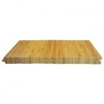
What I have found is bamboo flooring material (natural and carbonized). These panel are 915 - 960 mm (L) x 96 - 125 mm (W) x 10-15 mm (thickness). They have tongue and groove joint on the long sides to attached the "planks" with one another.
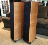
One route I can take is build the box using 12 mm or 15 mm material, and then glue on the 10 mm / 15mm bamboo planks over the box side panels. The flooring pieces will not be able to cover the 1150 mm vertical height of the speaker, so will probably have to orient the pieces horizontally, a bit like the Sonus Faber Cremona M (picture attached).
Another worry is that the planks have "micro-bevels" on all sides to give them that tiles look and feel, not sure how prominent these are, as I am seeking more of a "one sheet" look. From the image it looks like the Cremona M has very thin slits/grooves between each on the panels, so might not be a bad thing altogether.
And the plan is to make a rectangular box - not fancy boat hull shape.
Let me know what you guys think, and also if there are any structural strength concerns.
Hi Elsinore builders,
I've been trying to get hold of bamboo ply for a long time, but no luck...
What I have found is bamboo flooring material (natural and carbonized). These panel are 915 - 960 mm (L) x 96 - 125 mm (W) x 10-15 mm (thickness). They have tongue and groove joint on the long sides to attached the "planks" with one another.
One route I can take is build the box using 12 mm or 15 mm material, and then glue on the 10 mm / 15mm bamboo planks over the box side panels. The flooring pieces will not be able to cover the 1150 mm vertical height of the speaker, so will probably have to orient the pieces horizontally, a bit like the Sonus Faber Cremona M (picture attached).
Another worry is that the planks have "micro-bevels" on all sides to give them that tiles look and feel, not sure how prominent these are, as I am seeking more of a "one sheet" look. From the image it looks like the Cremona M has very thin slits/grooves between each on the panels, so might not be a bad thing altogether.
And the plan is to make a rectangular box - not fancy boat hull shape.
Let me know what you guys think, and also if there are any structural strength concerns.
Attachments

Zman
From an engineering standpoint, the tongue and groove joint horizontatally oriented acts effectively as a pinned connection structurally, so that there would be a loss of vertical stiffness of the enclosure wall compared with a monolithic material or the bamboo ply oriented with the grooves vertically oriented. Of course there is a vertical brace that provides stiffness, so perhaps you can compensate with modifying the internal bracing to compensate for the loss. But do not know if stiffness in the vertical direction is more critical.
David
PCB xover
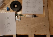
On the topic of xover PCBs I have just received mine. This PCBs are based on Ian's (irext) design. He was kind enough to send me his files some time ago but I could not get them to open properly so I just redraw from his pictures from post #2026. No holes since I will drill them myself.

On the topic of xover PCBs I have just received mine. This PCBs are based on Ian's (irext) design. He was kind enough to send me his files some time ago but I could not get them to open properly so I just redraw from his pictures from post #2026. No holes since I will drill them myself.
Zman
From an engineering standpoint, the tongue and groove joint horizontatally oriented acts effectively as a pinned connection structurally, so that there would be a loss of vertical stiffness of the enclosure wall compared with a monolithic material or the bamboo ply oriented with the grooves vertically oriented. Of course there is a vertical brace that provides stiffness, so perhaps you can compensate with modifying the internal bracing to compensate for the loss. But do not know if stiffness in the vertical direction is more critical.
David
David,
Thank you for your inputs.
If built the cabinet with 18 mm good quality ply, it should be stiffer than (or at least as stiff as) one built with 25 mm MDF?
So, if I build the cabinet with 18 mm plywood and then use 10 mm bamboo material as cladding with horizontal orientation, do you see this affecting the vertical stiffness of the 18 mm plywood cabinet structure?
I would be better off stiffness wise without the bamboo cladding glued on?
Last edited:
Hamlet Update:
My PCBs are due right now and may even be delivered today. I will use them to complete the Hamlet Mk6... so those who have been so patient, we are getting real close. Speaker design is not a fast process. You have to put in the time and elbow grease. So now I can finish the design. You guys can also make your own PCBs, but please don't use my layout without coming to me. Yes, some PCBs I may sell, but that is not the main reason for getting them made. I may decide that a bit later on.
I do have the H-Mk6 crossover design from the modeling and of course, it looks like the earlier Hamlet, but around half or more of the values have changed. And there are no unknowns that it shouldn't work as before (intimately familiar with these two drivers already). I could give you guys the crossover design right now, but I should have it built and get the Hamlets here working here and make sure that there are no final small changes required. In-room RTA testing and listening.
The voltage sensitivity is pretty much the same as the Elsinores, but where the Elsinores are remarkably flat 6 Ohm, the Hamlets will be flat 4 Ohm. Both very easy to drive, but you knew that anyway. The Hamlet may well be the easiest to drive 4 Ohm design anywhere in the world? Ultra-Tube friendly with amps with 4 Ohm taps. The Elsinores seems best suited to 8 Ohm taps.
Cheers, Joe
Last edited:
How about that thread, Joe. Pop a link in your sig so we can see it.
....would you please create a vendors thread for continuing discussion (Note 5 & 6)
Hi Allen, not ready for that and hasn't even been decided. I bought this batch mainly for my own needs.
It was a "Hamlet Update", because my completion of the Hamlet Mk6 was waiting for this board.
There is also the matter of the 'special' L4 inductor to suit this board, they should be here next week. Maybe this should be ordered by DIY'ers as a combo: Two boards and two inductors together, one price?
Then there is packing. Australia Post has a parcel box 240x190x120 mm I hope works. I also hope I can come up with one price wherever everybody pays the same. Oz guys pay the same as the US or EU etc. That's what I did with the waveguides and AP has a box 220x160x70mm that I use for that purpose.
We shall see. But others have made PCBs (all I ask that they don't copy my design). That's free!
Cheers, Joe
Last edited:
Hi
I'm thinking about building a set of Elsinores and a Hamlet.
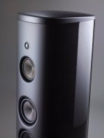
But the design of the front is a bit to square for me and I would really like to give it some curves in the style of the Magico M3 or the Børreson Z5
That means adding on an additional 20mm front on top of the drivers.
Having a large chamfer in front of the woofers and adding an extension to the exiting horn.
The horn is a copy of the original horn/waveguide for the first part and then goes out to a much wider part.
I know this isn't what was originally designed for. But how bad do you guys and gals think I'm screwing up the frequency response?


I'm thinking about building a set of Elsinores and a Hamlet.
But the design of the front is a bit to square for me and I would really like to give it some curves in the style of the Magico M3 or the Børreson Z5
That means adding on an additional 20mm front on top of the drivers.
Having a large chamfer in front of the woofers and adding an extension to the exiting horn.
The horn is a copy of the original horn/waveguide for the first part and then goes out to a much wider part.
I know this isn't what was originally designed for. But how bad do you guys and gals think I'm screwing up the frequency response?
David,
Thank you for your inputs.
If built the cabinet with 18 mm good quality ply, it should be stiffer than (or at least as stiff as) one built with 25 mm MDF?
So, if I build the cabinet with 18 mm plywood and then use 10 mm bamboo material as cladding with horizontal orientation, do you see this affecting the vertical stiffness of the 18 mm plywood cabinet structure?
I would be better off stiffness wise without the bamboo cladding glued on?
18mm baltic birch ply is as stiff as 25mm MDF, so think adding bamboo should fine, and the bamboo will still add additional stiffness. Don't know about damping effects. The added mass and change in stiffness properties will have an impact on the resonance frequency and amplitude of the enclosure walls compared with the original construction. All theoretical, no idea if will be significant at all to the sound.
David
Hi
I'm thinking about building a set of Elsinores and a Hamlet.
But the design of the front is a bit to square for me and I would really like to give it some curves in the style of the Magico M3 or the Børreson Z5
Nice looking eye candy. Sorry for the delay getting back, got plenty of distractions here.

The main issue, and it has come up before, is the any curving or rounding, if too much, can tilt the response due to the fact that the original design and the crossover values decided upon, are based on actual acoustic measurements with the drivers mounted in the box shown in the DIY project.
It is primarily the front baffle, and it is more about the width than the height. The L1 3.9mH inductor may need to be reduced to 3.5mH to compensate, but if you make that decision, it is estimated and not modelled, that is the difference.
Cheers, Joe
..also note that IF the baffle is fully curved (a'la Magico M3) the waveguide will either be slightly inset with a reflective vertical "lip" OR "proud" of the baffle horizontally with a diffractive horizontal "drop" to the baffle. You could of course shape the baffle for those vertical reflective "lips" to be non-existent, but that would require some mighty fine wood-working (..like perhaps with a CNC machine). The same is also true of the midbass driver's on the Elsinore with a baffle like the M3 (though it would likely be a bit less problematic).
And remember: the waveguide is more similar to the midrange's diameter than the tweeter shown on the M3:
And remember: the waveguide is more similar to the midrange's diameter than the tweeter shown on the M3:
Attachments
Last edited:
Hi Joe if I build Elsinore with rounded corners (5 mm
radius) will there be problems with the frequency response?
Thank you
Luca
radius) will there be problems with the frequency response?
Thank you
Luca
Nice looking eye candy. Sorry for the delay getting back, got plenty of distractions here.
The main issue, and it has come up before, is the any curving or rounding, if too much, can tilt the response due to the fact that the original design and the crossover values decided upon, are based on actual acoustic measurements with the drivers mounted in the box shown in the DIY project.
It is primarily the front baffle, and it is more about the width than the height. The L1 3.9mH inductor may need to be reduced to 3.5mH to compensate, but if you make that decision, it is estimated and not modelled, that is the difference.
Cheers, Joe
There is no delay. Remember this is just a hobby. You really don't have to be on here all day long!
That doesn't sound too discouraging. But of course I know there comes a bit of work with the change. I'll be measuring the frequency response to see how much the change did to the sound
I currently have 5 versions of the waveguide to figure out which one works most like the original
And I'll share the CAD files ones I'm done (Probably in the winter time) for anyone foolish enough to do what I did
..also note that IF the baffle is fully curved (a'la Magico M3) the waveguide will either be slightly inset with a reflective vertical "lip" OR "proud" of the baffle horizontally with a diffractive horizontal "drop" to the baffle. You could of course shape the baffle for those vertical reflective "lips" to be non-existent, but that would require some mighty fine wood-working (..like perhaps with a CNC machine). The same is also true of the midbass driver's on the Elsinore with a baffle like the M3 (though it would likely be a bit less problematic).
And remember: the waveguide is more similar to the midrange's diameter than the tweeter shown on the M3:
I'm working on a CNC, so I'll be trying out different waveguides and go from there. All based on the design of the original waveguide in terms of placement depth and angle
And lets just see where it takes me. Mad or brilliant, I don't know yet.
Hi Joe if I build Elsinore with rounded corners (5 mm
radius) will there be problems with the frequency response?
Thank you
Luca
Hi Luca. We have built them with not too large radius and not a problem. I am soon getting some boxes professionally made and they will have around a 5mm radius. So go right ahead.
Hamlet Update:
I have received all the parts I need to complete the Hamlet crossover. So around this time next week, we might be cooking (listening). Re the PCB, whether to make them available, not made that decision yet. I have thirty, but that means only 15 pairs. These are mated to 18mH Jantzen inductors (they are the largest component) and I also got thirty, so that means 15 pairs as well. So they should go together?
The photos will reveal a bit more. The values I have ordered to finish crossover, I hope the values will work out perfectly, it is mostly about L2 being the right value and that gets determined by using RTA in-room measurements and of course listening.
Cheers, Joe
I have received all the parts I need to complete the Hamlet crossover. So around this time next week, we might be cooking (listening
). Re the PCB, whether to make them available, not made that decision yet. I have thirty, but that means only 15 pairs. These are mated to 18mH Jantzen inductors (they are the largest component) and I also got thirty, so that means 15 pairs as well. So they should go together? The photos will reveal a bit more. The values I have ordered to finish crossover, I hope the values will work out perfectly, it is mostly about L2 being the right value and that gets determined by using RTA in-room measurements and of course listening.
Cheers, Joe
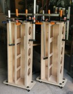
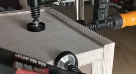
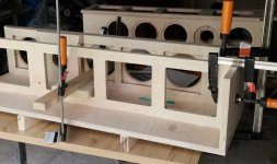
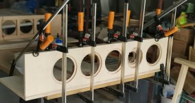
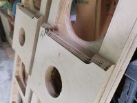
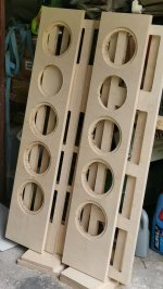
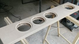
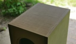
And another pair of Elsinore on their way to the salons. Since these sets will be playing in my studio on the second floor, I wanted to make them as mobile as possible.
I chose 21mm plywood. So there were changes in the dimensions of the box. Exterior maintained. Internal ones have been corrected by 4mm. As a result, I made a mistake and a dimple was created in the upper part. Nothing dangerous but I was wondering for a while how to fix it. Finally, I completed the filling with thin pieces of plywood. I milled the whole thing and I think I did something cool by accident.
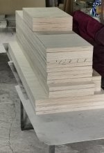
All that remains for me is a plinth for the housings in which I will place the crossover. It will be a demountable element, which will allow me to reduce the weight during transport.
The time it took me to make the boxes this time is incomparably shorter. Previously, I had reached this stage in three months. Now in two weeks It was enough to optimize the activities well.
I chose 21mm plywood. So there were changes in the dimensions of the box. Exterior maintained. Internal ones have been corrected by 4mm. As a result, I made a mistake and a dimple was created in the upper part. Nothing dangerous but I was wondering for a while how to fix it. Finally, I completed the filling with thin pieces of plywood. I milled the whole thing and I think I did something cool by accident.
All that remains for me is a plinth for the housings in which I will place the crossover. It will be a demountable element, which will allow me to reduce the weight during transport.
The time it took me to make the boxes this time is incomparably shorter. Previously, I had reached this stage in three months. Now in two weeks
It was enough to optimize the activities well.Attachments
- Home
- Loudspeakers
- Multi-Way
- The "Elsinore Project" Thread