You should not expect your measurements to agree unless you duplicate the manufacturer's measurement setup.
But like pre- and post- break-in TSPs, if both sets lead you to similar boxes and tunings, you are both probably doing a reasonably good(though different) job of it.
But like pre- and post- break-in TSPs, if both sets lead you to similar boxes and tunings, you are both probably doing a reasonably good(though different) job of it.
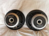
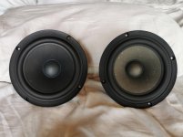
thats really strange for me that nobody cares or dont do any measurements of ts of drivers (parameters are really important and this is not revelator drivers where was really everything good with it) / i was having some issues with Sb dealer and after the main office of Sb sent me new pairs directly from indonesian factory and when they came they was looking different from what i was having before and also i noticed that on new pairs the speaker suspension is stiffer (it seems like one is foam rubber another is just like rubber) - i can guess and thats can only be my guess that because this loudspeker is not available no more they used suspensions from nrxc2 on the factory
thats really strange for me that nobody cares or dont do any measurements of ts of drivers (parameters are really important and this is not revelator drivers where was really everything good with it) / i was having some issues with Sb dealer and after the main office of Sb sent me new pairs directly from indonesian factory and when they came they was looking different from what i was having before and also i noticed that on new pairs the speaker suspension is stiffer (it seems like one is foam rubber another is just like rubber) - i can guess and thats can only be my guess that because this loudspeker is not available no more they used suspensions from nrxc2 on the factory
are you sure that you order the correct driver, post the picture of the driver name tag here. that is a very bogus assumption that SBA mix from one to another driver parts, you are not dealing with chinese cheap manufacturer
I wasnt measuring myself - i gave them to a company who are specialised on measurings - fs is normal for a new driver it will go down after it will break in but anyway it will never come close to datasheet - i think it will fall down to 35 ghz maximum / q is normal too / vas is really strange/
I also asked the company to measure another drivers which i was having before - truthfully all with very different serial numbers but normally breaked in/
so are the results
1
Fs = 35.61 Hz
Re = 5.60 ohms[dc]
Le = 60.62 uH
L2 = 723.53 uH
R2 = 3.95 ohms
Qt = 0.41
Qes = 0.45
Qms = 5.01
Mms = 13.07 grams
Rms = 0.582999 kg/s
Cms = 0.001529 m/N
Vas = 32.34 liters
Sd= 122.72 cm^2
Bl = 6.025226 Tm
ETA = 0.31 %
Lp(2.83V/1m) = 88.59 dB
2
Fs = 34.89 Hz
Re = 5.60 ohms[dc]
Le = 59.25 uH
L2 = 794.84 uH
R2 = 3.94 ohms
Qt = 0.43
Qes = 0.46
Qms = 5.24
Mms = 18.50 grams
Rms = 0.773625 kg/s
Cms = 0.001125 m/N
Vas = 23.80 liters
Sd= 122.72 cm^2
Bl = 6.987975 Tm
ETA = 0.21 %
Lp(2.83V/1m) = 86.85 dB
3
Fs = 38.52 Hz
Re = 5.60 ohms[dc]
Le = 62.79 uH
L2 = 718.40 uH
R2 = 4.27 ohms
Qt = 0.44
Qes = 0.47
Qms = 7.23
Mms = 9.13 grams
Rms = 0.305557 kg/s
Cms = 0.001870 m/N
Vas = 39.55 liters
Sd= 122.72 cm^2
Bl = 5.108969 Tm
ETA = 0.46 %
Lp(2.83V/1m) = 90.27 dB
as u can see even sensitivity is really different - so how it will sound this is a question and can i use this drivers in one setup
/ ofcos this drivers is from low budget and cant compare with satori drivers in identical parameters
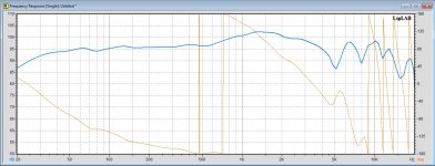
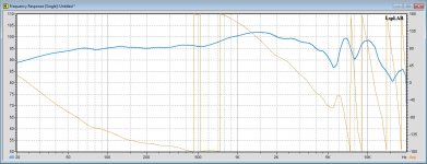
even that ts parameters are differ but frequency response looks not so bad
Trust me on this please, you will be fine. The Fs will come down after a while, it is mostly the 'spider' part of the suspension that needs a good workout. As the Fs gradually lowers, the Vas will increase. The interesting thing is that when the Fs hasn't yet fully lowered, the Vas will be lower, this means that the box 'looks' bigger to the driver (please don't ask me for a long explanation, but back in the 80's a guy whose name escapes me wrote an article about this) and this means that the box will push up the Fs less high. So low Vas does to a degree compensate for a high Fs while the driver (the spider) gets worked in and more supple. It will get where it needs eventually.
When measuring T-S Parameters, if I was to do that with my Clio setup, I can choose 1V and up to 6V stimulus. Guess what, the Fs will be lower as the stimulus goes up and the Vas will also go up. So a similar 'dance' goes on here. Oh well, nothing's perfect, but it still works.
It's actually current, so typically with 1V you are looking at 150mA and with 6V we are looking closer to an Amp. Too low and ambient noise can be a problem. Also very low level does not approximate what the driver has to do in real life. But as I said, there are some compensations happening due to Fs and Vas varying and off-settings, so I have decided not to lose too much sleep because it seems to work well with good drivers. 
Is there a design change coming?
Think "PCB" - and it isn't a drug although it sounds like it.
Is there a design change coming?
Polychlorinated biphenyl
Work in progress. Hush-hush!
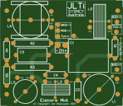
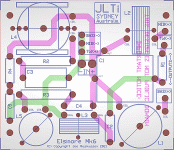
Please take note of Copyright, this is not public domain property. This is not yet the final design.
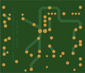
Very thick 2.5mm is likely but will affect cost. Suitable for both Elsinore & Hamlets. No availability date yet.
See attachments below.
Attachments
Last edited:
Not sure re the final price, let us see how it goes. It needs to be the same no matter where they are worldwide, just as everybody is paying the same for the Waveguides. The local post office sells padded bags 215 x 280mm and must be less than 20mm thick and it can be sent as a letter.
It will have mounting holes that allow it to be fitted to the two rear vertical braces at the back near the input terminals. Or it can be fitted to the bottom of the cabinet below near where the port is. Yes, I want it to be a heavy-duty PCB because t needs to support some heavy coils and other components and not vibrate. Yes, it costs more, but it's needed IMO. The coils can be fitted with cable ties and a dab of silicone where it interfaces with the board to prevent vibrations. You can of course fit it outside the speaker and even put it in its own box, some like that.
The board is designed to have as short as possible the most critical tracks, so a LOT of effort has gone into the layout. Interaction between coils to has been minimised and so on, and yet keep it 'small' enough to fit.
I would like feedback from others here, would something like this be helpful?
Looks interesting Joe. Not sure how I’d fit the big 20/4mH Erse inductors. But I’ve been looking to redo the crossover and it would be great to have a foolproof way to get it right again.
I have been working on the basis that the inductors (which I will list) are from Jantzen will work. That includes the large 18mH inductor.
I have been looking at an inductor from Intertechnik (they do Audyn caps like True Copper) that is a little smaller and potentially less expensive and 3.74R DC resistance and the series resistor then uses 3R3 10W to get a total of 7R as per the target. This inductor does not need to have low resistance, it is in fact wasted in both size and money. It has a hole in the centre and should be easy to mount. Even if you use components that are a bit on the big side, I am sure DIY'ers will still adapt for it and the PCB still be useful. But there are components out there that will fit this board and good quality at that. The most important are C1 (1.8uF), R1 (2R), L2 (1mH in MFC crossover) and L1 (4mH). In pretty much that order.
- Home
- Loudspeakers
- Multi-Way
- The "Elsinore Project" Thread
