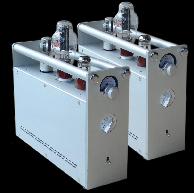
Those are quite pretty
Beauty is in the eye of the beholder, I wonder if the same can be said for ears....
") , to me they have quite a brutal, industrial look.
, to me they have quite a brutal, industrial look.Do you still want to proceed, I could point you in the right direction?Anyway, the Bolserst mod... I now see there were enough changes in the 2012 crossover to the MK6 that I cannot determine any parts list...
Beauty is in the eye of the beholder, I wonder if the same can be said for ears....
I think they look better than many other tube amplifiers.. pretty though: probably not.
(..reminds me of a "poor-mans" Nagra vertical tube amp.)What they do have is:
1. NOT a 12ax7 (input) gain stage.
2. SET (as opposed to push-pull)
3. DHT (for the output with the 300b)
4. tube rectifier.
5. dual mono chassis.
-of course they lack power, so the Elsinore's couldn't play very loud, and only moderately loud with modest non-linear distortion.
Since we are using dynamic loudspeakers, where the sound emanating from the individual driver is proportional to the current of the amplifier (whilst voltage 'causes' current to flow due to potential, we never are directly listening to the voltage of the amplifier, rather to the 'caused' current that flows through the voice coil.
So really then, amplifiers of all kinds are just different ways of delivering current to the speaker, and hence they are all current delivery systems.
The above fact is confirmed by the LIVE! with PURIFI Co-Founder Lars Risbo! - YouTube link that I posted earlier. As I have mentioned, I have been very interested in the Purifi drivers and their approach to isolate and understand distortion mechanisms and finding solutions to "impedance modulation" and "force fact modulation" as well as "surrounds" as causing distortion. Alas, the current Purifi drivers do not suit the Elsinores, but those three distortion mechanisms are well controlled (suppressed) in the Elsinores, but in different ways that a single Purifi driver does. I do it by using multiple drivers instead. But the mechanisms are the same even if the solution is different.
It is "impedance modulation" that is mentioned first. Suppress this by keeping inductance constant with excursion at any frequency. This is done using internal control of the inductance of the Purifi driver itself, but alas leads only to low inductance. I instead used and a driver with ultra-low inductance and the add an external inductor three times that of the driver itself. Indeed I believe my solution is superior to theirs.
This is where the SB17MFC35-8 driver comes in.
So many want me to upgrade to a more expensive driver and maybe come out with a more expensive version Mark 7. But that driver has an incredibly ultra-low inductance that few drivers have - in fact it is state-of-the-art. I measure 0.2mH at 1KHz and 0.075mH at 10KHz (the Purifi is 0.4mH and 0.2mH respectively) and adding 0.5mH per driver (1mH in total) make the "impedance modulation" suppressed because the inductance is stable with both frequency and excursion of the driver).
The "force factor modulation" and "surround" distortion issues are suppressed by four drivers in series-parallel below 400 Hertz (and hence reduced excursion 8:1 lower for any chosen dB/m SPL). Lower excursion of 8:1 reduces these two distortions, for example with 50Hz and 1KHz IMD measurements, for any target dB/m SPL.
The SB17MFC35-8 measured the critical 5th harmonic (and used as a rough indicator of the even worse 7th harmonic) are -80dB with respect to 95dB/m SPL. That is 0.01% distortion.
The Elsinore is a very low distortion speaker!
And the science backs it up. Yes, measurements and listening do sometimes agree, provided we are measuring the things that matter - when you get it right, measurements and actual listening results do agree.
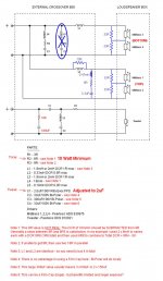
The below attachment shows a circuit of an amplifier (values to come later, we shall see) that is mainly designed with current in mind. According to Tim de Paravicini, an output transformer driven from a zero impedance is largely distortion-free. The below circuit uses this idea by running the output tubes near Unity Gain (1.5x) and the lowest possible impedance. The linearity is superb and 100mA on the Anodes into 20:1 transformer produces 2 Amp. The output transformer is actually a step-up current delivery device. This amplifier is designed to be a current delivery system. The driver only sees that current even if a voltage develops across its terminals.
Now that I have stated the above, I will not engage in any cantankerous exchange.
Accept the above as a "statement of intent" behind the work done. Anybody else can do it their way, no problem with me.
Cheers, Joe
So really then, amplifiers of all kinds are just different ways of delivering current to the speaker, and hence they are all current delivery systems.
The above fact is confirmed by the LIVE! with PURIFI Co-Founder Lars Risbo! - YouTube link that I posted earlier. As I have mentioned, I have been very interested in the Purifi drivers and their approach to isolate and understand distortion mechanisms and finding solutions to "impedance modulation" and "force fact modulation" as well as "surrounds" as causing distortion. Alas, the current Purifi drivers do not suit the Elsinores, but those three distortion mechanisms are well controlled (suppressed) in the Elsinores, but in different ways that a single Purifi driver does. I do it by using multiple drivers instead. But the mechanisms are the same even if the solution is different.
It is "impedance modulation" that is mentioned first. Suppress this by keeping inductance constant with excursion at any frequency. This is done using internal control of the inductance of the Purifi driver itself, but alas leads only to low inductance. I instead used and a driver with ultra-low inductance and the add an external inductor three times that of the driver itself. Indeed I believe my solution is superior to theirs.
This is where the SB17MFC35-8 driver comes in.
So many want me to upgrade to a more expensive driver and maybe come out with a more expensive version Mark 7. But that driver has an incredibly ultra-low inductance that few drivers have - in fact it is state-of-the-art. I measure 0.2mH at 1KHz and 0.075mH at 10KHz (the Purifi is 0.4mH and 0.2mH respectively) and adding 0.5mH per driver (1mH in total) make the "impedance modulation" suppressed because the inductance is stable with both frequency and excursion of the driver).
The "force factor modulation" and "surround" distortion issues are suppressed by four drivers in series-parallel below 400 Hertz (and hence reduced excursion 8:1 lower for any chosen dB/m SPL). Lower excursion of 8:1 reduces these two distortions, for example with 50Hz and 1KHz IMD measurements, for any target dB/m SPL.
The SB17MFC35-8 measured the critical 5th harmonic (and used as a rough indicator of the even worse 7th harmonic) are -80dB with respect to 95dB/m SPL. That is 0.01% distortion.
The Elsinore is a very low distortion speaker!
And the science backs it up. Yes, measurements and listening do sometimes agree, provided we are measuring the things that matter - when you get it right, measurements and actual listening results do agree.
The below attachment shows a circuit of an amplifier (values to come later, we shall see) that is mainly designed with current in mind. According to Tim de Paravicini, an output transformer driven from a zero impedance is largely distortion-free. The below circuit uses this idea by running the output tubes near Unity Gain (1.5x) and the lowest possible impedance. The linearity is superb and 100mA on the Anodes into 20:1 transformer produces 2 Amp. The output transformer is actually a step-up current delivery device. This amplifier is designed to be a current delivery system. The driver only sees that current even if a voltage develops across its terminals.
Now that I have stated the above, I will not engage in any cantankerous exchange.
Accept the above as a "statement of intent" behind the work done. Anybody else can do it their way, no problem with me.
Cheers, Joe
Attachments
Last edited:
With respect to a more expensive version:
Biggest limitation IMO is the tweeter, while superb objectively it's a bit "edgy" and over-damped subjectively.
still,
..you could use the SB17CRC35. It's not as ultra-low in distortion as the Purify drivers, but it is a fair-bit better than the poly-cones.
If you really wanted to cater to the "no-expense" crowd there are the Elipticore drivers from Scan Speak..
Do you still want to proceed, I could point you in the right direction?
Sure, no absolutely! The quest for perfection is never ending.. pm or here whatever works
Thank you!
Those are quite pretty
dave
Very Quatermass.
The CRC are too low sensitivity?
They are within +/- .5 db of each other.
Arguably, they are easier to correct than the poly's as well.
The horribly expensive Scan Speak Elliptical's are quite a bit better while also being about 2db more efficient. Still, the driver's are around 7x the cost of the CRC and around 13x the cost of the poly.
Last edited:
Not that I know of.. and really, that's the only area where Joe makes any money for people outside of Australia (..and likely many in Australia as well).
You could of course look it over and try to model it yourself (..in Fusion 360, FreeCAD, etc.).
Elsinore Speakers DIY
You could of course look it over and try to model it yourself (..in Fusion 360, FreeCAD, etc.).
Elsinore Speakers DIY
If can print my own I will Paypal Joe some rightly deserved compensation.
Let me get back to you shortly.
If Joe doesn't mind (PM sent), I'll prepare a little something on the topic.pm or here whatever works
I'm working off downloaded datasheets so hoping I have chosen the right parts.
The situation was originally described by Joe this way..
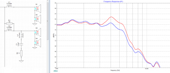
The first thing I wanted to do was to see if I could duplicate what bolserst had done. So I traced the axial response to use in the sim. The 33Ω resistors have a small effect, not so much to the shape of the response. To keep things simple I have left them out.
In the third attachment I've shown the normal response in red, and the modded response is in blue.
AudioFanMan, do your Mk6 use the SB17NRXC35-8 or the SB17MFC35-8?
The situation was originally described by Joe this way..
The original mod is shown in the first attachment. bolserst had this to say..Joe Rasmussen said:the best performance comes from a listening distance of at least two metres and approximate 15 degrees off axis. Hence set up the speakers reasonable well apart and hopefully no closer that 50cm from the rear wall. Aim the speakers towards the listener but no more than the listener can see the inside wall.
From here you can experiment with the width of the placement and also if you wish, the degree of toe-in towards the listener.
What is clear is that, if the speaker is pointed directly towards the listener (both of them of course) then expect there to be an excess of energy centered around 4KHz.
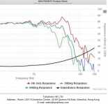
The Mk5 is shown with the Peerless HDS driver. The second attachment shows the variations at different angles due to cone breakup.bolserst said:tpate was troubled by this excess energy and after we measured his Mark 5, I modeled the crossover and suggested the attached modification for his crossover. For builders that find their listening setup to highlight the excess woofer energy around 4kHz, this modification might prove to be beneficial.
tpate is currently using this modification and has been very pleased with the results in his setup with both solid state and tube amplifiers.
The first thing I wanted to do was to see if I could duplicate what bolserst had done. So I traced the axial response to use in the sim. The 33Ω resistors have a small effect, not so much to the shape of the response. To keep things simple I have left them out.
In the third attachment I've shown the normal response in red, and the modded response is in blue.
AudioFanMan, do your Mk6 use the SB17NRXC35-8 or the SB17MFC35-8?
Attachments
AudioFanMan, do your Mk6 use the SB17NRXC35-8 or the SB17MFC35-8?
I use the newer SB17MFC35.
May be I should let you know why Im interested in testing this out as well, I have tried hard to take care of my hearing, knowing tinnitus and other nastys could be waiting for me down the road. I was the guy at the concert wearing ear plugs... So I have noticed of late during long sessions (regardless of volume level) I start to get the dreaded ringing in my ears. I think I may have taken one too many long distance tours on the Harley
I cant quite pin down what frequency's bother me, and it doesn't happen all the time. In the descriptions I read it removed the excess energy around 4k. The 33Ohm resistors I understood it as balancing out the speakers if there were differences between them, and this (Stage 1) is something Id like to try for sure. Im not looking to re-invent the design, I believe Joe has probably the design that is perfect for 99.9% of the folks (accounting for almost every variable), but as a tinkerer (#1) and someone who cant stop trying to fix what isn't broke (#2)
My room is not near ideal, my intermittent hearing issue, and the nagging voice saying if I don't try it, Ill never know...
I plan on a "temporary" setup just to try…
That said, I almost feel like the 33 ohm resistors or Stage 1, wouldn't hurt and could only help. The fact that I have to remove the drivers, Im hoping they cant hurt....
That sounds good, we're just experimenting
I got the MFC traces from here - https://www.madisoundspeakerstore.com/pdf/SB17MFC35-8.pdf
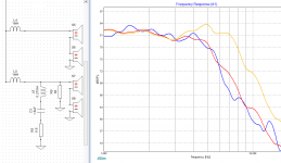
Using the axial plot again to maintain consistency. I started by adding the resistors to the old bolstert mod (blue trace) to use as a reference target if nothing else. The MFC with normal crossover is shown (orange plot). The modified MFC is shown in red.
Phase is within 45 degrees of the original and follows a similar line. If this mod seems to make too much difference, try doubling the 6.8 ohm resistor, even quadrupling it. It will bring you in steps back toward the original response.
I got the MFC traces from here - https://www.madisoundspeakerstore.com/pdf/SB17MFC35-8.pdf
Using the axial plot again to maintain consistency. I started by adding the resistors to the old bolstert mod (blue trace) to use as a reference target if nothing else. The MFC with normal crossover is shown (orange plot). The modified MFC is shown in red.
Phase is within 45 degrees of the original and follows a similar line. If this mod seems to make too much difference, try doubling the 6.8 ohm resistor, even quadrupling it. It will bring you in steps back toward the original response.
Attachments
Thank you so much!! I will work on the parts list this weekendThat sounds good, we're just experimenting
- Home
- Loudspeakers
- Multi-Way
- The "Elsinore Project" Thread