Yes. It is correct. And basically it shouldn't affect the sound. Well, except in the case of tube amplifiers. My amp is very strong. There should be no changes.
And yet something can be heard differently. I'm not sure, but I think the lower midrange is fuller. More tangible.
I guess everyone has to find out for themselves. And evaluate. For the moment I leave the crossover without this correction. I have easy access to the crossover, so let me experiment a little more.
This is weird. With a an amplifier that has very low output impedance, the impedance compensation in the xover should not matter at all.
What is the output impedance of you amp?
Are you SURE the impedance compensation networks were set up correctly?
This is weird. With a an amplifier that has very low output impedance, the impedance compensation in the xover should not matter at all.
What is the output impedance of you amp?
Are you SURE the impedance compensation networks were set up correctly?
I will have something to say about shortly. Think about this for a moment, why is most of the Voice Coil out the gap in 99.999% of all speakers made? There is something hiding in plain sight.
Will get back shortly...
.
This is weird. With a an amplifier that has very low output impedance, the impedance compensation in the xover should not matter at all.
What is the output impedance of you amp?
Are you SURE the impedance compensation networks were set up correctly?
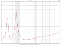
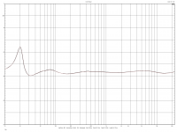
Connecting the compensation circuit is very simple. I see no error. When I put the whole thing together, I took measurements with and without the crossover.
Measurement of the mid-woofers themselves in the box. And measurement together with the crossover.
I do not know the output impedance of the EX-7M.
Yes, it is weird. There should be no change. Of course, I take into account that I have succumbed to some self-suggestion. Therefore, I need time to research this situation. And if anyone has such an opportunity, check it at home.
It's not that there is more to music. That something is not louder. It is expressive. It's hard to describe. But I definitely like it.
It takes time to tame it. Just to be sure it does change.
Attachments
Last edited:
Think about this for a moment, why is most of the Voice Coil out the gap in 99.999% of all speakers made?
Voice coil overhang is there to improve the linearity of the driver motor. I don't see how this has to do with the impedance compensation networks, which are in parallel to the xover+driver.
On the other hand, the compensation networks do interact with the xover+driver and with the amplifier. While the following may be a bit math heavy for some, it is just the conventional and well-accepted wisdom based on well-accepted physics (Ohms Law and Kirchhoffs Laws):
- Vout is the output voltage of the amplifier.
- Iout is the output current of the amplifier.
- Rout is the output impedance of the amplifier (this includes the resistance of the loudspeaker cables between the amplifier terminals and the xover).
- Z0 as the complex impedance of the entire loudspeaker (driver in box, xover, impedance compensation networks)
- Z1 as the complex impedance of the driver+xover (without the compensation networks).
- Z2 is the complex impedance of the compensation network(s).
The current output from the amplifier is Iout = Vout / (Z0+Rout).
The voltage across the loudspeaker terminals is V0 = Vout - Rout x Iout, and hence V0/Vout = Z0/(Z0+Rout).
If Rout is not negligibly small, the amplifier / loudspeaker form a voltage divider system. If Z0 varies with frequency (as with most loudspeakers), the voltage divider formed by the amplifier / loudspeaker is variable with frequency, too. This means that the frequency response of the entire system is modulated by Z0, which will affect the sound reproduction. To counter-effect this problem, impedance compensation networks are used in parallel to the xover+driver (Z1) to remove (or at least to reduce) the frequency dependence of Z0.
With the compensation networks in place, the impedance of the entire loudspeaker is:
Z0 = Z1 || Z2 = Z1 x Z2 / (Z1 + Z2)
The trick is to design the compensation networks such that Z2 balances the frequency variation of Z1, and hence results in an (almost) constant Z0.
If Rout is very small (much smaller than Z0), Z0/(Z0+Rout) = 1 and hence V0 will be equal to Vout, and Z0 will not modulate the frequency response of the amplifier / loudspeaker system. This means that the sound is not affected by the loudspeaker impedance as long as the output impedance of the amplifier is (very) low.
Therefore, assuming that JarBars amp really does have low output impedance, I do not understand how/why JarBar observed a clear sonic difference with / without the impedance compensation networks. Maybe the cables used in between the amp and the speakers were very long or thin (resulting in high Rout)?
So if the Elsinores will be used with subs, as in my case, the cabinets can be built as closed boxes with the two LCR's removed or recalculated to whatever Qtc you choose to use?
Cool to see another in Sweden building Elsinore's. My boxes are ready right now, have had parts for them for years. I'm building a pair of mk5 with 830875 drivers.
About to order the waveguides and last parts for crossover today.
Think about the following for a moment.
Inside a typical driver you have the following element. You have a magnetic circuit made up of a magnet (donut shaped squared), a rear plate, a front plate and a centre pole. These are arranged to focus into a round narrow gap that the voice coil sits inside, this is connected to a cone (or dome) which has a mechanical suspension that allows movement along a specific axis, backwards and forwards.
Take a close look at the voice coil. The driver we use, SB17MFC35-8 or SB17NRXC35-8, these are essentially the same drivers, only the cone material is different. So the number crunching we shall use will be from those drivers. I am trying to attempt something that might seem controversial, but it shouldn't be, and the surprise conclusion at the end.
Note where it says "Voil coil and gap" and look closely that some part of the coil sticks out at the front of the gap and some at the rear. This is usually described as "Xmax" but not always. If specced as such, the the maximum linear travel will be 2 x Xmax, typically 2 x 5mm = 10mm linear travel max.
Now let us look at our Elsinore Voice Coil specs.
Voice coil diameter 35.5 mm
Voice coil height 16 mm
Air gap height 5 mm
Linear coil travel (p-p) 11 mm
Let us for simplicity say that this is a single layer voice (even though it has two, it does not change the point we want to make) and we see that the single layer VC is 16mm long, but the gap is only 5mm, thus Xmax is 5.5mm and the max linear coil travel is correctly stated to be 11mm.
Everything looks clear here, right? But sometimes the truth can hide in plain sight. This is where it gets interesting:
If we apply an amplifier's voltage across the Voice Coil, let us say 10V RMS, that voltage is distributed across the whole of the coil. The force factor is only applied inside the gap. That means that only 3.125V appears inside the gap (5/6*10=3.125) and that is problematic to our thinking that we are "listening to the voltage of the amplifier" when we are in effect listening to only 31% of its voltage.
Indeed, if the excursion exceeds 11mm peak-to-peak, that voltage goes down even lower. That this causes distortion should not surprise anybody. Now even less voltage is seen inside the gap. But is that what is causing distortion? It seems so to many, but the answer is definitely is NO! It is because the full gap is not 'filled' and hence the current of the amplifier results in reduced force factor inside the gap. It is the current of the amplifier going through the voice coil, not its voltage, flowing through the Voice Coil, this is what we are listening to.
Clearly, we should never go beyond the 11mm max linear travel, so at least we know that 31% of the voltage is inside the gap. But how much of the current is inside the gap. Let us assume that our load is the same as the DC resistance of the voice coil and make that a simple 6 Ohm (it is actually 5.7). So that would make the current
What is clear is we have 1.666 Amp and it flows through the entire coil. Where is the current coming from? The amplifier of course. It is 10V/6R = 1.666 Amp. This current comes from the amplifier.
So this raises a curious question:
Are we listening to 31% of the voltage of the amplifier "and" 100% of the current of the amplifier?
The answer is not "and" at all. There is no "and" because the answer is obvious and not a matter of choice.
We are listening to the 100% of the current of the amplifier and not its voltage.
And why should that surprise us? Only a partial voltage appears across the gap, whereas the current goes through the entire Voice Coil will be constant 1.666 Amp at all time. Provided that the max linear travel is not exceeded, the current going through the coil will be fairly constant. The voltage is not constant, the current is.
In late 2018 I sat down and had a conversation with a person, who is also a scientist and physicist with extraordinary expertise in magnetics, who also happens to be a tube amplifier designer and designs his own magnificent transformers. He is even a serious musician. What I said was not a question, I made the statement:
"We are listening to the current of the amplifier, not its voltage."
He did not blink but answered:
"And soon we shall be able to prove that is the case. The answer is definitely there."
We now are able to prove it and able to explain that is a fact. It will be resisted, but the physics are right and so are the numbers too. These include actual distortion measurements of current induced distortion and explains how it is caused.
When nearly 69% of the coil is outside the gap at any one time, that means in our case 4.14 Ohm of the DC resistance sits passively on either side of the coil and 2.07 Ohm on either side of the coil when linear motion is very small. This 4.14 Ohm is is series with the likely series inductor, the speaker cable and the output impedance of the amplifier and guess which is the dominant value?
What this means is that ALL amplifiers, even if they are 'voltage' sources, they are ALL just different ways of supplying current to the loudspeaker.
ALL amplifiers are current delivery systems. It does not matter whether the are solid state or tube, voltage sources or current sources. Track what the current does (and this is what we have done) and that is what you hear. It pretty much explains everything the voltage model does, but it also answers questions that the voltage model never will.
Of course there will be resistance to this view.
The Elsinores as a design, is affected by the above and the way they have been designed is to maximise what the current does and the beauty is that it works with all amplifiers - keep in mind, the is current EQ and that the current phase angle will always be zero degrees... so I have not told the whole story yet.
-
Inside a typical driver you have the following element. You have a magnetic circuit made up of a magnet (donut shaped squared), a rear plate, a front plate and a centre pole. These are arranged to focus into a round narrow gap that the voice coil sits inside, this is connected to a cone (or dome) which has a mechanical suspension that allows movement along a specific axis, backwards and forwards.
Take a close look at the voice coil. The driver we use, SB17MFC35-8 or SB17NRXC35-8, these are essentially the same drivers, only the cone material is different. So the number crunching we shall use will be from those drivers. I am trying to attempt something that might seem controversial, but it shouldn't be, and the surprise conclusion at the end.
An externally hosted image should be here but it was not working when we last tested it.
Note where it says "Voil coil and gap" and look closely that some part of the coil sticks out at the front of the gap and some at the rear. This is usually described as "Xmax" but not always. If specced as such, the the maximum linear travel will be 2 x Xmax, typically 2 x 5mm = 10mm linear travel max.
Now let us look at our Elsinore Voice Coil specs.
Voice coil diameter 35.5 mm
Voice coil height 16 mm
Air gap height 5 mm
Linear coil travel (p-p) 11 mm
Let us for simplicity say that this is a single layer voice (even though it has two, it does not change the point we want to make) and we see that the single layer VC is 16mm long, but the gap is only 5mm, thus Xmax is 5.5mm and the max linear coil travel is correctly stated to be 11mm.
Everything looks clear here, right? But sometimes the truth can hide in plain sight. This is where it gets interesting:
If we apply an amplifier's voltage across the Voice Coil, let us say 10V RMS, that voltage is distributed across the whole of the coil. The force factor is only applied inside the gap. That means that only 3.125V appears inside the gap (5/6*10=3.125) and that is problematic to our thinking that we are "listening to the voltage of the amplifier" when we are in effect listening to only 31% of its voltage.
Indeed, if the excursion exceeds 11mm peak-to-peak, that voltage goes down even lower. That this causes distortion should not surprise anybody. Now even less voltage is seen inside the gap. But is that what is causing distortion? It seems so to many, but the answer is definitely is NO! It is because the full gap is not 'filled' and hence the current of the amplifier results in reduced force factor inside the gap. It is the current of the amplifier going through the voice coil, not its voltage, flowing through the Voice Coil, this is what we are listening to.
Clearly, we should never go beyond the 11mm max linear travel, so at least we know that 31% of the voltage is inside the gap. But how much of the current is inside the gap. Let us assume that our load is the same as the DC resistance of the voice coil and make that a simple 6 Ohm (it is actually 5.7). So that would make the current
What is clear is we have 1.666 Amp and it flows through the entire coil. Where is the current coming from? The amplifier of course. It is 10V/6R = 1.666 Amp. This current comes from the amplifier.
So this raises a curious question:
Are we listening to 31% of the voltage of the amplifier "and" 100% of the current of the amplifier?
The answer is not "and" at all. There is no "and" because the answer is obvious and not a matter of choice.
We are listening to the 100% of the current of the amplifier and not its voltage.
And why should that surprise us? Only a partial voltage appears across the gap, whereas the current goes through the entire Voice Coil will be constant 1.666 Amp at all time. Provided that the max linear travel is not exceeded, the current going through the coil will be fairly constant. The voltage is not constant, the current is.
In late 2018 I sat down and had a conversation with a person, who is also a scientist and physicist with extraordinary expertise in magnetics, who also happens to be a tube amplifier designer and designs his own magnificent transformers. He is even a serious musician. What I said was not a question, I made the statement:
"We are listening to the current of the amplifier, not its voltage."
He did not blink but answered:
"And soon we shall be able to prove that is the case. The answer is definitely there."
We now are able to prove it and able to explain that is a fact. It will be resisted, but the physics are right and so are the numbers too. These include actual distortion measurements of current induced distortion and explains how it is caused.
When nearly 69% of the coil is outside the gap at any one time, that means in our case 4.14 Ohm of the DC resistance sits passively on either side of the coil and 2.07 Ohm on either side of the coil when linear motion is very small. This 4.14 Ohm is is series with the likely series inductor, the speaker cable and the output impedance of the amplifier and guess which is the dominant value?
What this means is that ALL amplifiers, even if they are 'voltage' sources, they are ALL just different ways of supplying current to the loudspeaker.
ALL amplifiers are current delivery systems. It does not matter whether the are solid state or tube, voltage sources or current sources. Track what the current does (and this is what we have done) and that is what you hear. It pretty much explains everything the voltage model does, but it also answers questions that the voltage model never will.
Of course there will be resistance to this view.
The Elsinores as a design, is affected by the above and the way they have been designed is to maximise what the current does and the beauty is that it works with all amplifiers - keep in mind, the is current EQ and that the current phase angle will always be zero degrees... so I have not told the whole story yet.
-
Last edited:
Joe, I am not sure I see your point(s).
First, it has always been clear since the invention of the electrodynamic speaker 120 years ago that the accelerating force of the cone is caused by the current flowing through the voice coil, not by a voltage. I don't think any knowledgeable person would doubt this. The voice-coil current is the result of the voltage applied to the voice coil voltage. Also, vice versa, a current induced in the voice coil causes a voltage across the coil. The current and voltage are linked to each other by the electrical impedance of the driver. It's a bit like gravity: not exactly a new thing.
Second, I don't think the whole story is very different with underhung voice coils, except that the full voice coil is in the gap.
Third, and maybe most interesting to me, how does all this relate to the original question if/how impedance compensation networks might affect the sound even if the output impedance of the amplifier is very low?
Actually it's not that simple, we listen to the sound coming from the movement of the cone not the electrical signal however you want to measure it.
Define 'electrical signal' and why we are not listening to it. You mean the cone is excited all by itself. Have you heard of Kirchoff's Law?
Don't bother answering, you have been a troll all along. Sorry I even have to say that, but in a "No Facts World" I am becoming used to it.
Like I predicted, there will be opposition, even if the physics is correct.
Expect no further comment. I will let you have the last word and just ignore it, your reputation precedes you.
-
...how does all this relate to the original question if/how impedance compensation networks might affect the sound even if the output impedance of the amplifier is very low?
Look at the current phase angle and ask if the source is Class AB, what is the result? There is research going on re this very point and the result is high order distortion. It will come out eventually.
Re underhung voice coils, it is the the current even if the Voice Coil sees the entire voltage of the amplifier. It makes no difference, we are still listening to the current of the amplifier, period!
Why is this so controversial? I don't get it. The physics are all so clear. So what is really going on?
We truly live in a strange world, on so many levels. Sigh.
-
I'm only interested in the facts, not opinions. The facts will be in the acoustic measurements and how they correlate. Loudspeakers are very complex devices, to say we hear the current is wrong.
No comment. History will get it right in the end. They correlate!
-
I'm glad to hear you've taken acoustic measurements, it will be interesting to see them and how they correlate.
Good! I was hoping you would say that, I am the eternal optimist. Things, despite COVID and all that, despite major family problems and dealing with severe mental health issue in my son, it has still been a productive year in other ways. We are actually getting a team together on this and they include some serious people with science clout. You are absolutely right about the issue of 'correlation' of the electrical versus acoustic side, indeed Scott Wurcer has made the same deduction and confronted me with it - and he is absolutely right about that. I have good news and it will come out, but it will not be via www.diyaudio.com, it will be done in a way via proper peer review. This will be a marathon and not a sprint. I just hope my health bears up long enough, I am probably older than you think, I will be 69 on December 3rd.
-
Pavel did some measurements as you recall. It's not in dispute that some form of impedance matching can often be beneficial, I think people have only ever wanted to see what is actually going on.
Totally agree!
And I have given Pavel credit for what he did. I have taken things to the next level. His conclusion, which I think Esa Merilainen has also taken, is that the dynamic driver is more linear under current drive (I am not a current drive proponent, I just want to know what the current is doing) and I think that conclusion is not quite right. I think we have to take a closer look at what the amplifier is doing. For example, at 2KHz I have a driver here that has 29 degrees current phase angle when connected to a voltage source, yet it has zero degrees current phase angle when connected to a current source. Does this mean that a current source is superior? Pavel and Esa are basically saying yes. But I am asking questions about that difference in current phase angle and chasing it down, with the help of a few friends who are not dummies, and something else is gradually emerging and it is truly fascinating. But what it reveals is not new, it was true all the time and why are we surprised that it should be different?
For example, the Q of a system at LF can be defined accurately by both maths and measurement by measuring current versus frequency and is the rationale behind some of the current EQ used in the Elsinores (I would love you to hear them). I have a friend who is looking at a new equations that will conform with the Qes equation [Qes=(2Pi*Fs*Mms*Re)/Bli^2]. Note that "i" is a component of current and that voltage is not mentioned in Thiele's equation. This is about adding to our understanding, not substituting nor eliminating. I never met Thiele, but we had a mutual friend.
It's 1.50AM here, gotta get my beauty sleep.
")
I'm glad to hear you've taken acoustic measurements, it will be interesting to see them and how they correlate.
A gold star for your perseverance, or maybe we should create a new award the "Hachi Medal". A very sad story of a dog that waited at the train station every day for 11 yr. for a master that died suddenly at work.
@mbrennwa - The introduction of complex math is futile.
Look at the current phase angle and ask if the source is Class AB, what is the result? There is research going on re this very point and the result is high order distortion. It will come out eventually.
I still don't see the point. I guess you'll tell us more when your thoughts are ready.
Re underhung voice coils, it is the the current even if the Voice Coil sees the entire voltage of the amplifier. It makes no difference, we are still listening to the current of the amplifier, period!
Why is this so controversial? I don't get it. The physics are all so clear.
Joe, for some reason you keep saying it's controversial, but I simply don't see a controversy! It's just silly to claim that the "current drives the cone" idea is controversial. The Lorentz force is surely not a controversial concept.
Maybe you conceive it as a "controversy" if some people (rightly) object to your statement of "what we hear is the current". What we hear is sound waves, not an electrical current (at least my ears have no ability for sensing of electrical currents). The sound is created by the vibrations of the cone, which is the result of electrodynamic forces (among others), which in turn result from the voice-coil current.
- Home
- Loudspeakers
- Multi-Way
- The "Elsinore Project" Thread