Can't the tweeter be moved forward by 7mm To bring it flush?
Bob, if you use the plywood you hav ebeen using in your other flat-paks i se eno issue with all 18mm, it will still be bettre than 25mm MDF.
dave
...miters are doable ...
I am not a big fan of mitres, dadoes yes (they increase glue area, but more imporantly make it harder to assemble them wrong.
dave
Placement of Iron core inductors ?
Well, thought my 45 deg router bit was big enough, dunno what I was thinking. So while I wait for Amazon...
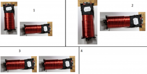
Laying out my crossover. Have to say, I'm a bit intimidated. Been worrying about coil placement, have a ton of parts and it looks like a very limited amount of room.
I have digested all I can with the excellent layout guide for air coils, but am unsure of how an Iron core is affected.
If what I have learned is correct, and Iron core while having more inductance with less turns, produces a smaller field as the concentration is actually in the core itself. Did I get this acculturate ?
I believe Joe said somewhere that L4 wasn't super critical to have air core, and all I could find in stock was 4 10Mh iron core's.
So, I need to layout 2 in series, and which of the attached would you consider the better layout. If they all are bad, please don't be bashful !
Well, thought my 45 deg router bit was big enough, dunno what I was thinking. So while I wait for Amazon...
Laying out my crossover. Have to say, I'm a bit intimidated. Been worrying about coil placement, have a ton of parts and it looks like a very limited amount of room.
I have digested all I can with the excellent layout guide for air coils, but am unsure of how an Iron core is affected.
If what I have learned is correct, and Iron core while having more inductance with less turns, produces a smaller field as the concentration is actually in the core itself. Did I get this acculturate ?
I believe Joe said somewhere that L4 wasn't super critical to have air core, and all I could find in stock was 4 10Mh iron core's.
So, I need to layout 2 in series, and which of the attached would you consider the better layout. If they all are bad, please don't be bashful !
Attachments
Flux leakage tests do produce unexpected results from time to time. Apply common sense with an extra dose, unless you are constrained for space and then rely on your test equipment. (BTW, the word 'bad' used in the image you quoted to indicate coupling could be a little misleading. Keep it in perspective.)
I'm trying to come up with as small of a footprint as I can, and plan on hanging the x-over off the back of the speaker.
That said, are you saying my results with my #2 is unexpected ?
Only checking because I did not spend a ton on the LCR meter and the common sense you speak of may be common for folks who have done this a bunch of times...
Flux leakage tests do produce unexpected results from time to time. Apply common sense with an extra dose, unless you are constrained for space and then rely on your test equipment. (BTW, the word 'bad' used in the image you quoted to indicate coupling could be a little misleading. Keep it in perspective.)
That said, are you saying my results with my #2 is unexpected ?
Only checking because I did not spend a ton on the LCR meter and the common sense you speak of may be common for folks who have done this a bunch of times...
Unexpected, not unexpected. Sometimes these measurements are simple and sometimes it's like trying to isolate room modes.are you saying my results with my #2 is unexpected ?
Why not repeat your attempt. While you do it, try moving things around to see what influences your results. See if making noise or bumping the bench changes the results.
Hello irext,
Determining placement and orientation for minimum coupling between coils by ear:
THIS!!!
Wow, followed the amazing write up by bolserst above, and its absolutely amazing. The T shaped layout of the Iron core inductors matters within a tenth of an inch. There is most certainly a "sweet" spot where the flux leakage is kept to an absolute minimum.
Whats troubling is the air core inductor needs to be way out in never never land. When I am able to secure the almighty and indispensable alligator clips I can see I have a good hour of testing to go.
Word for anyone who like me is going through this for the very fist time.
Place the inductors on a bench top, leave every other crossover component in the parts bag. Concentrate first only on avoiding cross talk. Then, work out the rest ....
45 chamfer done
Amazon came through, got my big honkin 45 bit, believe I'm done with the router !
Dang 8-32 x 1.5" cap head screws for speaker mounting turned out to be 10-32! Now waiting on another delivery as I already have the 8-32 thunder bolts.
Cut all the parts for the x-over's boxes... waiting on lexan and 1/8" tempered hard board in another delivery.
Believe I have a coil layout that's as optimal as can be for the size enclosure it will be in, have a teeny tiny bit of optimizing to do, will post what I came up with after. Hint, Iron Core indutcors also benefit from tilting off horizon")
Would never have known unless I actually tried using amp+tone generator + moving to and fro up and down...
I believe I will be making speakers soon, instead of sawdust !
Amazon came through, got my big honkin 45 bit, believe I'm done with the router !
Dang 8-32 x 1.5" cap head screws for speaker mounting turned out to be 10-32! Now waiting on another delivery as I already have the 8-32 thunder bolts.
Cut all the parts for the x-over's boxes... waiting on lexan and 1/8" tempered hard board in another delivery.
Believe I have a coil layout that's as optimal as can be for the size enclosure it will be in, have a teeny tiny bit of optimizing to do, will post what I came up with after. Hint, Iron Core indutcors also benefit from tilting off horizon
Would never have known unless I actually tried using amp+tone generator + moving to and fro up and down...
I believe I will be making speakers soon, instead of sawdust !
Attachments
Last edited:
Never had any issues with hurricane nuts. You can always pull them back in if they start to spin on the inside (but that never happened to me).
Parts Express #10-32 Hurricane Nuts 50 Pcs.
I have seen these. What size thread do they use? Is it metric or imperial?
Joe,
There's an explanation on #10-32 screw size here - does this help?
Difference between 10-32, 12-24, and M6 threads - RackSolutions
AudioFanMan,
Good to see progress happening.
There's an explanation on #10-32 screw size here - does this help?
Difference between 10-32, 12-24, and M6 threads - RackSolutions
AudioFanMan,
Good to see progress happening.
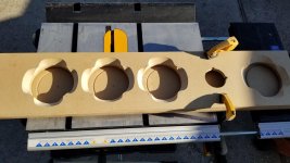
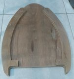
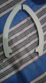
made few cuts on the template using plywood and i find that the back curve can be connected directly. so another new template have been ordered with front 'ear' have been widened to 30mm
with 40mm side wall, i can get 80L internal volume on 115cm height.
with 40mm side wall, i can get 80L internal volume on 115cm height.
Attachments
Hi all,
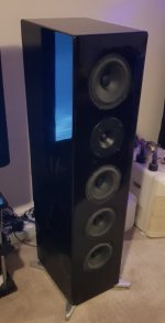
Well it's been somewhat of an epic. I started my Elsinore build in mid 2016. I completed stage 1 (assembled in MDF) a few months later and brought them in for a trial period. In August last yearrolleyes: yep!) I finally pulled them apart again to finish the cabinets. The original build, while solid, had a number of flaws that had to be corrected. So anyhow, after a months of pretty solid work, I now almost finshed. I went for a fairly traditional build. I used auto laquer and the results came out quite well. I used BMW Carbon Black which is an excellent dark blue pearl metallic that looks mostly black until you see them in stronger light. I have completed one and due to a persistant paint issue, am now in the home straight for completing the other. Many mistakes were made, but considering these are essentially prototypes built without a proper workshop (or skill really), they came out quite well. There are a few things to improve yet, but it feels very good to (almost) have a good friend returning to the house.
I now have the full spec JLTi Oppo 105 -> Headamp GSX2 -> latest spec Joe EL34 tube amp and into the Elsinores. Joe completed the builds for me a few months ago, so I have been frustrated without any speakers for some time.
Upon completion, I will do a little show and tell with learnings that will hopefully benefit others looking to complete this great project.
Well it's been somewhat of an epic. I started my Elsinore build in mid 2016. I completed stage 1 (assembled in MDF) a few months later and brought them in for a trial period. In August last year
rolleyes: yep!) I finally pulled them apart again to finish the cabinets. The original build, while solid, had a number of flaws that had to be corrected. So anyhow, after a months of pretty solid work, I now almost finshed. I went for a fairly traditional build. I used auto laquer and the results came out quite well. I used BMW Carbon Black which is an excellent dark blue pearl metallic that looks mostly black until you see them in stronger light. I have completed one and due to a persistant paint issue, am now in the home straight for completing the other. Many mistakes were made, but considering these are essentially prototypes built without a proper workshop (or skill really), they came out quite well. There are a few things to improve yet, but it feels very good to (almost) have a good friend returning to the house. I now have the full spec JLTi Oppo 105 -> Headamp GSX2 -> latest spec Joe EL34 tube amp and into the Elsinores. Joe completed the builds for me a few months ago, so I have been frustrated without any speakers for some time.
Upon completion, I will do a little show and tell with learnings that will hopefully benefit others looking to complete this great project.
Attachments
- Home
- Loudspeakers
- Multi-Way
- The "Elsinore Project" Thread