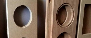
Doesn’t look like you have any chamfer at all on the back of the cut-outs. You do not wan tthe driver sitting ain a cyclindrical tunnel. It will screw up lots of things but mids the most. Got a big *** 45° router bit? And the hole in the back baffle should be what the inner side of the hole on the front baffle is (or even a bit bigger).

Joe had a very good expalnation of his rationale for a rectangular cutout on the inner baffle, and you seem to have done it in the worst way possible.
You only have to have one t-nut spin out when you try to take the driver out and you will understand why.
I have 7 KEF B200 captive in a box at this moment for that reason. I did get lucky w one.
dave
Joe had a very good expalnation of his rationale for a rectangular cutout on the inner baffle, and you seem to have done it in the worst way possible.
...I picked up T-nuts but hear folks like the Hurricane nuts...
You only have to have one t-nut spin out when you try to take the driver out and you will understand why.
I have 7 KEF B200 captive in a box at this moment for that reason. I did get lucky w one.
dave
Attachments
Doesn’t look like you have any chamfer at all on the back of the cut-outs. You do not wan tthe driver sitting ain a cyclindrical tunnel. It will screw up lots of things but mids the most. Got a big *** 45° router bit? And the hole in the back baffle should be what the inner side of the hole on the front baffle is (or even a bit bigger).
You only have to have one t-nut spin out when you try to take the driver out and you will understand why.
I have 7 KEF B200 captive in a box at this moment for that reason. I did get lucky w one.
dave
Thank you for your input!
And yes, I do have a 45, will run it round... The hole is already bigger than the speaker cut out. Also, Im working with 3/4" thick material not 1". So, I have 1.5" thick while Joe's design is 2". The 1/2 less offers me (I believe) a little more clearance.. But warning heeded..
Ok Im hearing all on the T-nuts, loud and clear.
Has anyone tried the Hurricane Nuts ?
The bamboo is only 3/4 and after insetting figure the boo is close to 1/2".
I dont want to rely only on 1/2" of bamboo and know better than relying on the MDF.. Would feel better with a more positive connection...
I agree that the 1/2" material left over for mounting the SBA's is less than ideal (considering the lengths taken to mount the tweeter).
I may glue in 4 small blocks to give more material for mounting. Either that or leaving a little extra material at the middle the sides of sub-front panel to accept the bolts.
Are there better options than t-nuts or hurricane nuts. They don't seem that different.
I may glue in 4 small blocks to give more material for mounting. Either that or leaving a little extra material at the middle the sides of sub-front panel to accept the bolts.
Are there better options than t-nuts or hurricane nuts. They don't seem that different.
Last edited by a moderator:
And yes, I do have a 45, will run it round... The hole is already bigger than the speaker cut out. Also, Im working with 3/4" thick material not 1". So, I have 1.5" thick while Joe's design is 2". The 1/2 less offers me (I believe) a little more clearance.. .
Tried to edit this post, as the information is incorrect
EDIT! I remembered wrong, Joe's design is 1.684" thick, not 2" as written above...
Im certainly going to 45 most of the back. Will leave 4 "tabs" for mounting screws...
Notably the "Sub Front Panel" should have those rectangular cut-outs, NOT circular cut-outs.
So:
1. the baffle should have the circular chamfer on the interior of it's panel.
2. the "sub front panel" should have the larger rectangular cut-outs.
Elsinore Construction
..if you just have a circular cut-out for the "sub front panel" (chamfered or not) then you are going to screw up the result.
So:
1. the baffle should have the circular chamfer on the interior of it's panel.
2. the "sub front panel" should have the larger rectangular cut-outs.
Elsinore Construction
..if you just have a circular cut-out for the "sub front panel" (chamfered or not) then you are going to screw up the result.
Last edited:
Notably the "Sub Front Panel" should have those rectangular cut-outs, NOT circular cut-outs.
So:
1. the baffle should have the circular chamfer on the interior of it's panel.
2. the "sub front panel" should have the larger rectangular cut-outs.
Elsinore Construction
..if you just have a circular cut-out for the "sub front panel" (chamfered or not) then you are going to screw up the result.
I don't see the chamfer recommendation on Joe's construction for the front baffle.
He doesn't have that.. but it's not a bad idea to do this (..excepting of course the mount-points).
..at 18mm with inset it's probably not needed though. At 25mm it might be more important. (..and it also depends on the frame of the drivers - if there is a "lip" on the inside of the circular mount (rear of driver) then you can't do anything about that amount of extension of that "lip" - so the baffle doing the same isn't going to be a problem.)
..at 18mm with inset it's probably not needed though. At 25mm it might be more important. (..and it also depends on the frame of the drivers - if there is a "lip" on the inside of the circular mount (rear of driver) then you can't do anything about that amount of extension of that "lip" - so the baffle doing the same isn't going to be a problem.)
Note: after looking again at the square cut-out for the "sub front panel" - they absolutely should have chamfering. (..far more important than the baffle having the chamfering.) I didn't look at how close the square cut-outs for the sub-front panel were in relation to the drivers.

As to why the square vs circular cut-out for this board: circular is concentric - it groups the reflections and resonance, square isn't great - but it's a lot better than circular.
Last edited:
Note: after looking again at the square cut-out for the "sub front panel" - they absolutely should have chamfering. (..far more important than the baffle having the chamfering.) I didn't look at how close the square cut-outs for the sub-front panel were in relation to the drivers.
As to why the square vs circular cut-out for this board: circular is concentric - it groups the reflections and resonance, square isn't great - but it's a lot better than circular.
So you would not be concerned about the mids mounting to the 1/2" material left over after the recesses?
I'm assuming you are referencing the baffle..
I'd be less concerned about that, though I'd still want that chamfered as well (again, except the mounting points). The driver frame does look like it has a bit of a lip without that foam mounting ring/gasket - say 3mm's or about 1/5th the depth of the baffle (mount), so if correct I'd still want that chamfer.
This brings-up an interesting question: does Joe spec. the gasket mounting ring or not?
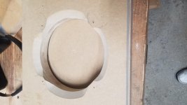
Rained most of the day, but had to kick up a little dust.. attached shows 2 passes with the 45, probably have 2 more to go but this is the general idea...
I understand this is no mans land, and im wrong frequently so ..
If sound is vibration in air, and movement, i believe a 45 degree offers less resistance than a 90. Well, i should say I know for a fact asking air to move through around 90 vs around a 45 creates much more resistance, turbulence and total equivalent lengths are much higher.
What i admit to know nothing about is sound frequency, standing waves and most of all, speaker building!
That said, i offer my self up to the gods of chance and plan to proceed. My hunch is, if im correct the nox will appear to be slightly largerand tuning the port length might be affected. I also think that i may have to hire a consultant to tweak cross over values (hint!) But won't know until I learn much more about testing the speakers...
That said, if anyone had to take a stab in the dark, and if my assumptions are correct, is a box appearing to be larger a bad thing?
Attachments
I'm assuming you are referencing the baffle..
I'd be less concerned about that, though I'd still want that chamfered as well (again, except the mounting points). The driver frame does look like it has a bit of a lip without that foam mounting ring/gasket - say 3mm's or about 1/5th the depth of the baffle (mount), so if correct I'd still want that chamfer.
This brings-up an interesting question: does Joe spec. the gasket mounting ring or not?
Yes...the front baffle. I suppose with a bamboo board front baffle it should be solid enough.
If sound is vibration in air, and movement, i believe a 45 degree offers less resistance than a 90. Well, i should say I know for a fact asking air to move through around 90 vs around a 45 creates much more resistance, turbulence and total equivalent lengths are much higher.
It depends on what frequency you are talking about. As the size of the “feature"
approaches the wavelength of the sound the affect becomes greater.
dave
..I suppose with a bamboo board front baffle it should be solid enough.
about 1/2" w/ 45 degree chamfers (except mount points): absolutely.
..particularly when you consider that the board is braced very close to those edges.Rained most of the day, but had to kick up a little dust.. attached shows 2 passes with the 45, probably have 2 more to go but this is the general idea...
-looks like you've got almost *3/4 inches of concentric "tunnel": not good.
(..peak resonance I'm guessing around 2.4 kHz.)*I'm assuming almost 1/2" of bamboo and at least a 1/4" of mdf from the picture.
Last edited:
-looks like you've got almost *3/4 inches of concentric "tunnel": not good.
*I'm assuming almost 1/2" of bamboo and at least a 1/4" of mdf from the picture.
Will be making more passes with a 45 deg. router bit to bring down to the 1/2", except for the mounting points...
My garage shop is kind of like 10 lbs of poop in a 2 pound bag.. Have to do all real dusty stuff outside..
Attachments

-looks like you've got almost *3/4 inches of concentric "tunnel": not good.
How did you come up with the 2.4 kHz number?
If I consider the "tunnel" as a tube with open ends, the resonance wavelength would corresponds to 2 x tube length. The corresponding wave length would be 38 mm, or 9 kHz. This is well beyond the pass band of the woofer, so it would be entirely irrelevant.
If I consider the "tunnel" as a tube with open ends, the resonance wavelength would corresponds to 2 x tube length.
A tube closed at one end is a 1/4 wave resonator, open or closed at both ends it is a 1/2 wave resonator.
A 1.5” deep tunnel closed at one end will have a 2.26 kHz resonance —assuming the driver closes one end. But of greater concern ar ehighish frequencies reflecting off that 90° edge back thru the cone.
dave
- Home
- Loudspeakers
- Multi-Way
- The "Elsinore Project" Thread