Hello Everyone-
I have gotten a design I think I like for Tang Bang’s W5-704s with a Dayton PT2B-8 Planar Tweeter. I already have the tweeter and was looking for a woofer that would be able to be crossed over at 4,000 Hz. I used the FRD Consortium tools. Traces are from Zaph's measurements.
I have to go back and re-run all of my simulations again, just to double check everything. I have played with some many internal volumes, tunings, baffle sizes and crossovers, I like to “rebuild” from scratch with what I think I settled with.
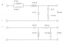
Here is where I am at. The internal volume is 17 Liters net. Baffle is 9-12/16”x14-11/16” with 3/4” edges. Woofer has an LR contour network for baffle step, a Zobel network and a 4,000 Hz lowpass filter. The tweeter has an approx. 15 dB L-Pad and a 2nd order electrical high pass filter at 4,000 Hz.
I have included some graphs from PCD and an Excel version with +/-1.5 & +/- 3 dB limits for reference.
THOUGHTS?
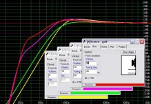
Excel Plot of Predicted Freq. Response:
PCD Plot:
Reverse Connection on the Tweeter:
Crossover:
REFERENCE THREAD:
http://www.diyaudio.com/forums/showthread.php?s=&threadid=20780
I have gotten a design I think I like for Tang Bang’s W5-704s with a Dayton PT2B-8 Planar Tweeter. I already have the tweeter and was looking for a woofer that would be able to be crossed over at 4,000 Hz. I used the FRD Consortium tools. Traces are from Zaph's measurements.
I have to go back and re-run all of my simulations again, just to double check everything. I have played with some many internal volumes, tunings, baffle sizes and crossovers, I like to “rebuild” from scratch with what I think I settled with.
Here is where I am at. The internal volume is 17 Liters net. Baffle is 9-12/16”x14-11/16” with 3/4” edges. Woofer has an LR contour network for baffle step, a Zobel network and a 4,000 Hz lowpass filter. The tweeter has an approx. 15 dB L-Pad and a 2nd order electrical high pass filter at 4,000 Hz.
I have included some graphs from PCD and an Excel version with +/-1.5 & +/- 3 dB limits for reference.
THOUGHTS?
Excel Plot of Predicted Freq. Response:
An externally hosted image should be here but it was not working when we last tested it.
PCD Plot:
An externally hosted image should be here but it was not working when we last tested it.
Reverse Connection on the Tweeter:
An externally hosted image should be here but it was not working when we last tested it.
Crossover:
An externally hosted image should be here but it was not working when we last tested it.
REFERENCE THREAD:
http://www.diyaudio.com/forums/showthread.php?s=&threadid=20780
It looks like the box is too big for the woofer looking at the droop followed by a big peak.
I'd put a notch filter on the tweeter's resonance and increase the slope of the tweeter, the phase tracking isn't too good looking at the tweeter reversed simulation.
Try oversizing the 0.37mH woofer inductor and adding a resistor in series with the 8.42uF capacitor to take care of the baffle step, less inductors in series with the woofer that way")
I'd put a notch filter on the tweeter's resonance and increase the slope of the tweeter, the phase tracking isn't too good looking at the tweeter reversed simulation.
Try oversizing the 0.37mH woofer inductor and adding a resistor in series with the 8.42uF capacitor to take care of the baffle step, less inductors in series with the woofer that way
Hi,
The box is far too big for the Vas of the driver, the driver does not suit vented loading.
If your going to use it you should go sealed and add an active subwoofer.
Your crossover is far too complicated and does not work very well
in controlling the ripple issues caused by the box, generally you do
not need a separate baffle step element in the crossover.
Wait for Zaph to publish his W5-704S/SD1.1 design for some pointers.
/sreten.
The box is far too big for the Vas of the driver, the driver does not suit vented loading.
If your going to use it you should go sealed and add an active subwoofer.
Your crossover is far too complicated and does not work very well
in controlling the ripple issues caused by the box, generally you do
not need a separate baffle step element in the crossover.
Wait for Zaph to publish his W5-704S/SD1.1 design for some pointers.
/sreten.The more I look at it, the more concerned I am that there is going to be a lack of bass in 100-400 Hz range. We are only talking a 1.5 dB though…
The box tuning has a ~3 db peak at tuning. I have decided to smooth it out a bit by lowering the tuning from 60 Hz to 50 Hz. If it had a perfectly flat response, it would be around 79 dB, so the rise you are seeing is the baffle step raise combined with the rise in the transducer itself.
I twill try that. What is the drawback of having inductance inline with the woofer? I am also going to try a 2nd-order slope. With the second order, I am hoping to smooth out some of the roughness in the 1-3 kHz range.
It looks like the box is too big for the woofer looking at the droop followed by a big peak.
The box tuning has a ~3 db peak at tuning. I have decided to smooth it out a bit by lowering the tuning from 60 Hz to 50 Hz. If it had a perfectly flat response, it would be around 79 dB, so the rise you are seeing is the baffle step raise combined with the rise in the transducer itself.
Try oversizing the 0.37mH woofer inductor and adding a resistor in series with the 8.42uF capacitor to take care of the baffle step, less inductors in series with the woofer that way
I twill try that. What is the drawback of having inductance inline with the woofer? I am also going to try a 2nd-order slope. With the second order, I am hoping to smooth out some of the roughness in the 1-3 kHz range.
The box is far too big for the Vas of the driver, the driver does not suit vented loading.I used Zaph’s measurements and the “design” volumes for both sealed and vented are huge. Sealed (w/ Qtc=0.707) is around 30 Liters (if I recall). At 17 L, a sealed enclosure at Qtc-0.74. Zaph send he is going to measure some more to see if there is a consistency issue. Zaph's measurements do differ from mfg. spec by a good margin.
If your going to use it you should go sealed and add an active subwoofer.
The speaker is going to be for my brother-in-law for his bedroom (he is finishing a large addition with a new master bedroom). They probably will not be played loud, but he is a fan of the bass, so I do want to try to stick with a vented enclosure. There is no plan for a sub.
Thanks for the pointers. I will give some a try and report back.
I have been using the free FRD Consortium tools.
Start with Baffle Diffraction Simulator and then input into Frequency Response Combiner that combines the predicted box response, actual freq response on an open baffle, with the baffle diffraction to get a overall frequency response.
Here is a good writeup on the procedure: RJB Audio
Start with Baffle Diffraction Simulator and then input into Frequency Response Combiner that combines the predicted box response, actual freq response on an open baffle, with the baffle diffraction to get a overall frequency response.
Here is a good writeup on the procedure: RJB Audio
Hi Sreten,
Why do you say that? Room gain? Woofer excursion below tuning frequency? All of the sims you posted have humps in the response, will those be boom boxes also? Just curious.
I have been playing with Unibox and have gotten what looks like a respondably flat response. The response does gradually raise approx. 2 dB from ~200 Hz to ~60 Hz.
Anything that looks flat will be a serious boom box.
Why do you say that? Room gain? Woofer excursion below tuning frequency? All of the sims you posted have humps in the response, will those be boom boxes also? Just curious.
I have been playing with Unibox and have gotten what looks like a respondably flat response. The response does gradually raise approx. 2 dB from ~200 Hz to ~60 Hz.
69stingray said:Hi Sreten,
Why do you say that? Room gain? Woofer excursion below tuning frequency? All of the sims you posted have humps in the response, will those be boom boxes also? Just curious.
I have been playing with Unibox and have gotten what looks like a respondably flat response. The response does gradually raise approx. 2 dB from ~200 Hz to ~60 Hz.
Hi,
None of them are going to sound wonderfully tight, the best 10L sealed.
Any attempt to get flat response below 100Hz will be a boom box
due to group delay at the port frequency if its say 50 to 60Hz, go
for 40Hz or below tuning in my book.
Use of room gain will bring up low bass if you keep the speakers
away from the walls, corners and floor, i.e. freespace mounting.
/sreten.Well….I have been playing around with PCD some more. I kept the Zobel on the W5-704s and the RL contour (baffle step) filter but changed from a 3rd-order to a 2nd-order filter. The sallow slope of the second-order helped to smooth out the roughness in the 1,500-3,000 Hz range. The planar tweeter also got a 2nd order filter. The 3rd-order helped suppress the baffle-step hump in it’s response but created more of a “hole” in the combined response.
I tried keeping the 3rd-order filter on the woofer and incorporating the baffle step into it (eliminating the RL filter) but just could not get there. Maybe if the cross-over point was lower (2-2.5 kHz) it might of doable.
Still playing with box size / tuning. I modeled a couple sealed enclosures and the response falls off too quickly I think (no plan for a sub).
Thoughts? I will try to post the revised crossover schematic shortly.
Attachments
I think your filter on the W5-704S is too complex. Try modeling it with just a single coil and a single cap. You may not get as steep of a rolloff, but you don't need it, since there is no serious cone breakup at higher frequencies.
Something else to try is adjust the microphone position in the spreadsheet. You will find that moving it around will cause DRAMATIC changes in FR. This can be useful to dial in the preferred listening angle. I like to flip the phase on the tweeter, then move the microphone position until the null is at it's deepest.
Dan
An externally hosted image should be here but it was not working when we last tested it.
An externally hosted image should be here but it was not working when we last tested it.
Take these into account when you do the design.
THe top graph shows the W5-704S top mounted response as well as surface mounted.
Then the lower graph shows the off axis response of the W5-704S.
These measurments were done by Mr G.R. Koonce when I had these drivers made for Nuera Acoustics. (long ago)
Enjoy
Where's the bass?
If your BIL likes bass, he's not going to be impressed with these little speakers, is he? 55Hz Fs? 3mm Xmax? 25W RMS power handling? Looks like a nice, smooth bookshelf speaker driver that NEEDS a sub.
(Except for your +/- 4dB peak/dip around 1.5k-2.2k. Why don't Zaph and RAW FR graphs have this ripple?)
Re: Where's the bass?
I believe it's because he summed the drivers FR with a baffle diffraction simulation.
Dan
Tosh said:(Except for your +/- 4dB peak/dip around 1.5k-2.2k. Why don't Zaph and RAW FR graphs have this ripple?)
I believe it's because he summed the drivers FR with a baffle diffraction simulation.
Dan
Re: Where's the bass? Post #17
quote:
Originally posted by Tosh
(Except for your +/- 4dB peak/dip around 1.5k-2.2k. Why don't Zaph and RAW FR graphs have this ripple?)
I believe it's because he summed the drivers FR with a baffle diffraction simulation.
Dan
Correct, Zaph’s FR has a 3 dB raise above 1,000 Hz, which lines up nicely with the hump in the baffle step, which at it’s peak, is close to 8 dB before leveling out at 6 dB. With that being said, there is some extra roughness between 1-4 kHz due to the ripple effect of the baffle step. There is approx. 8 db of baffle step to account for. I did try different baffle widths. Going smaller made it worst, going wider helped smooth out 2-4 kHz but I am already as wide as I would like to be.
Where's the bass? Post #16
If your BIL likes bass, he's not going to be impressed with these little speakers, is he? 55Hz Fs? 3mm Xmax? 25W RMS power handling? Looks like a nice, smooth bookshelf speaker driver that NEEDS a sub.
When I say he likes bass. I mean he likes his speakers to be a little more bass heavy then I would like. He is more use to big box store speakers that I think have a build-in bass hump. Yes, this is only a 5.25” driver, I do not think it is going to shatter any windows. In a sealed enclosure it, it rolls off around 100 Hz. The purpose of the port is just to fill-in under 100 Hz. This is a “bookshelf” type speaker and there are no plans for a sub. I picture some of those speakers that come with small shelf systems, those are usually ported……if the port is no good, it can be removed or plugged.
I think your filter on the W5-704S is too complex. Try modeling it with just a single coil and a single cap. You may not get as steep of a rolloff, but you don't need it, since there is no serious cone breakup at higher frequencies.
Thanks OWDI, I did try that with the 3rd-order crossover, just couldn’t get there. I will try with the second-order to see if it is possible to remove the RL network (which I would love to do!).
Here's what I managed to come up with for my Vifa XG18 + Seas 27TBFC/G OB using a total of 6 crossover components. I thought it would be much tougher to get good results with so few components, especially with the greater baffle diffraction issues caused by going OB.
Only the Vifa XG18 is OB. Baffle diffraction was modeled using the Edge. Since the Vifa XG18 is a midrange only, I am applying zero baffle step compensation.
Dan
Only the Vifa XG18 is OB. Baffle diffraction was modeled using the Edge. Since the Vifa XG18 is a midrange only, I am applying zero baffle step compensation.
An externally hosted image should be here but it was not working when we last tested it.
An externally hosted image should be here but it was not working when we last tested it.
Dan
Thanks Dan, I will have to study your crossover. I have had zero time this week to play with it. One thing I did notice, your crossover is a little lower then mine. I am trying to cross @ 4 kHz. I am thinking that may be why I am having trouble including the baffle step in the low-pass filter.
Nice looking impedance also!
Nice looking impedance also!
- Status
- This old topic is closed. If you want to reopen this topic, contact a moderator using the "Report Post" button.
- Home
- Loudspeakers
- Multi-Way
- Design Review: Tang Bang W5-704s Woofer