Has anyone tried implementing the log sweep speaker testing protocol described by Farina in this paper? I'm not clear about whether it's an option in any of the commercial packages.
In a nutshell, a five second long exponential sweep of frequency (but called a log sweep) is used as the speaker stimulus; it's an exponential chirp. Then a time reversed and exponentially weighted version of the stimulus is convolved with the speaker's response. The result of that convolution is the speaker's impulse response, but in a novel form. Instead of a single impulse a series of impulses is generated. The latest one reflects the speaker's linear response to the stimulus. The earlier pulses correspond to the nonlinear responses--the nonlinear distortion. By inverse fourier transforming each of the separate impulses you can look at the linear portion of the frequency response, untainted by harmonic distortion, or you can look at any order(s) of the harmonic distortion. One of the claims is that the more common MLS method generates frequency response measurements that can be corrupted by nonlinear distortion, while Farina's method is less prone to that problem. If my description is too garbled to make sense, take a look at Farina's paper. It contains a more thorough and careful description.
I decided to try my hand at creating a speaker testing program that uses Farina's approach. As of late last night I managed to get a LabVIEW-based program working, and the whole idea seems pretty slick. However, since I haven't yet had time to apply it while actually designing a speaker I wondered if there are down sides that I haven't thought of or encountered yet. Does anyone else have any experience with Farina's technique? Is there a good reason it hasn't taken the speaker testing world by storm?
Few
I don't know of any commercial packages that implement it directly, but there are several DIY versions that have floated around. I think Ed Wildgoose has a semi-portable version using either rtaudio or portaudio on his site (duffroomcorrection.com).
I had a partial implementation using BruteFIR, although I never quite got it automated - I had to manually select out the impulse from the resultant de-convolution, and didn't automatically compute distortion.
I agree though - very slick, and I'm surprised that it's not used more.
I had a partial implementation using BruteFIR, although I never quite got it automated - I had to manually select out the impulse from the resultant de-convolution, and didn't automatically compute distortion.
I agree though - very slick, and I'm surprised that it's not used more.
Thanks, I hadn't seen the approaches either of you mentioned. Very interesting. I'll probably continue on what seems to be becoming a quest to create DIY speaker testing software for DIY speaker design (where does it end??) but it's reassuring to know others have found this path worth pursuing.
I take it neither of you (neither dwk123 nor houstonian) have found some fundamental flaw that suggests I shouldn't waste my time with the Farina approach?
My next step is to automate the process of calculating the SPLs associated with the first few harmonic distortion products. I was encouraged to find that the impulse responses for each of the harmonics show up right where Farina's work predicted. I'm (naively?) hopeful that that will make the automation process easier than it would be otherwise. It'd be pretty cool to have a series of harmonic distortion measurements automatically generated every time I do what otherwise would have been a simple frequency response measurement. Anybody know a way also to extract a single coefficient that expresses how good the speaker will sound? That sure would simplify the process.")
I take it neither of you (neither dwk123 nor houstonian) have found some fundamental flaw that suggests I shouldn't waste my time with the Farina approach?
My next step is to automate the process of calculating the SPLs associated with the first few harmonic distortion products. I was encouraged to find that the impulse responses for each of the harmonics show up right where Farina's work predicted. I'm (naively?) hopeful that that will make the automation process easier than it would be otherwise. It'd be pretty cool to have a series of harmonic distortion measurements automatically generated every time I do what otherwise would have been a simple frequency response measurement. Anybody know a way also to extract a single coefficient that expresses how good the speaker will sound? That sure would simplify the process.
I'm not sure such coefficient exists at all.Originally posted by Few Anybody know a way also to extract a single coefficient that expresses how good the speaker will sound?
BTW, which platform (Linux, win32, other) will be used in your program? The thing is, 'qloud' has the only Linux-specific class, if I remember (as author) well, and your can try to migrate the app to win32, as all other things are cross-platform (Linux/win32).
As for commercial apps, ARTA (win32 app) can use Farina's method.
Yeah, the "good sound coefficient" was a weak attempt at a joke. It's just as well that no such thing exists--it would take all the fun out of it.
I intend to continue writing my own code, so my question really is more along the lines of whether others are using Farina's method, and whether there are any troubles with it that I should watch out for. My impression so far is that there are a few implementations out there, but it hasn't really become a standard method. If that's true, and the method has advantages over MLS-based systems, I'm curious about why the MLS systems are still the standard.
One feature of the log sweep I like is that it's possible to define the log sweep to start at any frequency so you're not forced to run low frequencies through a tweeter to test it. Obviously you can put a filter in series with the tweeter, but limiting the bandwidth of the stimulus seems like a more elegant solution. Plus, the idea that the various orders of harmonic distortion are neatly separated in time is just cool.
Few
That's what I've read, but doesn't it really only address harmonic distortion? I'm asking this without access to any resources to double-check my memory, so I could be just plain wrong. In any case, I don't think that other things that affect the quality of reproduction, things like the flatness of frequency response and the directivity, are addressed. In that sense there still isn't a single number to express how well a speaker reproduces sound. Of course all this discussion is just a result of my attempt to make an audio joke. Serves me right.
Thanks for reminding me that I do need to go back and read up on the GedLee work, though.
Thanks for reminding me that I do need to go back and read up on the GedLee work, though.
Listen Inc.'s "SoundCheck" and Liberty Instruments' "PRAXIS" both implement the Farina method. (I'm the programmer for PRAXIS, but I'll try to keep this from being an advertisement!).
It is a very powerful technique. Farina's paper had most to do with measuring harmonic distortion, which the technique does very well and really quickly. Another benefit (and more important to me) is that it allows quick measurement of the frequency response while rejecting harmonic distortion products. It is also more immune than MLS methods to time shift issues (such as air currents when measuring in a large space).
If you measure something that has significant distortion (such as, say, a loudspeaker playing at moderately high levels) with MLS, the recovered impulse response portrays harmonics as weird fake pulses that look randomly interspersed around the impulse response, which can't be separated from the real impulse response, and so can mess up a frequency response test. With the Farina technique, the impulse response shows all the harmonics in negative time (i.e., before the main impulse) where they can be easily removed without at all disturbing the main "linear" impulse response.
If you ever need to get a clean loudspeaker impulse response (with very low corruption from distortion) the Farina method (also called "Log-Swept" or "Log Chirp") is the way to go. There is a technique in my software that can use a clean impulse response of a speaker to calculate it's linear effects (i.e., only frequency response) on a pieced of music. Then, the music is actually played through the speaker and the calculated linear recording is subtracted from the actual recording -- leaving a recording of only the non-linear distortion!
There is also an unconventional dual Log-Swept way to measure intermodulation distortions using a variation on the Farina technique, though it's pretty complicated and not much used.
>One feature of the log sweep I like is that it's possible to define the log sweep to start at any frequency..
Actually, you can't do that with the Farina technique as described above - you need to be able to calculate an impulse response from the sweep, which you can't do without sweeping the entire band (DC to half the sample rate). You can make a log sweep that starts at higher frequencies, but you can't calculate the impulse response from it.
A better way to avoid hitting the tweeter with high energy is to just drive it through a small series capacitor, which cuts out the highs. You can easily (and very accurately) compensate for the frequency response effects in the measured result by also getting the "reference voltage sample" from the far side of the capacitor. The rolloff drops out in the calculation and everthing stays happy.
Why not? I do it in 'qloud'.bwaslo said:Actually, you can't do that with the Farina technique as described above - you need to be able to calculate an impulse response from the sweep, which you can't do without sweeping the entire band (DC to half the sample rate).
Thanks, guys, for the responses. Interesting point about the limited bandwidth log sweep idea. In my tests I've been starting the log sweep at 10 - 20 Hz, and I thought the resulting impulse response looked quite like what I was getting from MLS and true impulse tests. I have to admit I didn't do a quantitative comparison, so maybe any errors introduced by not including DC - 20 Hz in the stimulus just escaped my notice. What sort of symptoms should I expect if the bandwidth of the stimulus isn't wide enough---perhaps a false DC offset on the impulse, or a computed step response with the wrong decay time? I guess I was naively thinking that if the driver's response is negligible in a particular frequency range, then nothing would be lost by excluding that range from the stimulus. Something else to think about! Thanks.
BTW, Bill, I didn't realize PRAXIS incorporated this approach so thanks for setting me straight.
Few
BTW, Bill, I didn't realize PRAXIS incorporated this approach so thanks for setting me straight.
Few
dwk123 said:I don't know of any commercial packages that implement it directly
Fuzzmeasure on OS X uses it. I've been implementing it in my Labview speaker measuring code.
http://www.supermegaultragroovy.com/products/FuzzMeasure/
Sheldon
Well, it's not that you can't do it, you'll get an answer, just not a great one. Depending on how you do it, one of two things might happen: (and sorry in advance for the long-winded explanation)
If you start with a log chirp from near-dc, and gate out the earlier part from going through the speaker, and deconvolve it with the full log chirp, then the result will be as if the frequency response suddenly goes from nothing to something at the start frequency, which will give ringing in the impulse response. You can't go from something to nothing in the freq response without it showing in the time domain, and probably with a bad non-causal effect. Which isn't bad in itself if you only wanted the freq response at higher freqs and aren't going to window out any echoes. But to get from impulse response to frequency response without echoes you'd have to window (i.e., not FFT the whole IR). And if the window you use cuts into a nonzero part of the ringing, which is likely, that will add artificial ripples in the response.
If you deconvolve your chirp with the truncated chirp (the same waveform as is applied to the speaker) rather than with the full chirp, you won't get ringing but you'll probably get LF noise (low frequency ripples in the freq response), which also messes things up with windowing. The noise happens because there isn't much energy at low frequencies in the stimulus nor in the deconvolution waveform, its spectrum at low frequencies will be very low in energy. But your mic will pick up normal levels of noise at low frequencies, so the reference normalization will be dividing something nonzero and erratic by something pretty close to zero, which effectively boosts the noise way up.
[I'm assuming in the second scheme above that you normalize the measurement with the voltage applied to the speaker -- if you don't normalize (trusting that the soundcard and amp are flat enough that you don't need to remove their effects), then your impulse may actually be ok -- there is still a little energy there in the stimulus below the chirp start frequencies because of the abrupt start of the chirp, so it will be somewhat like a step-stimulated measurement there -weal stimulus, but nonzero at least. The noise at LF will still be high, but since you aren't looking to measure the LF response, no problem. Not doing the normalization will still leave some noise, but at least it won't get boosted out of sight by dividing by a small signal. ]
The main problem comes in in the windowing. If your half window cuts in where the impulse response waveform isn't zero, you'll be superimposing the spectrum of a transient that isn't there onto your freq response - sharp edges have HF energy.
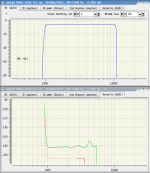
There are not problems. If you use limited frequency range (with smoothing at the edges) you _know_ you use limited range and neglect artefacts at the edges. This is SPL and harmonics for 'qloud' direct connection - program output is connected to program input (it is possible to do such connection with Linux JACK sound server). So, such connection tests the method itself. Just look at the values of harmonics. I'm sure there will not be sound cards (not saying about loudspeakers) with such resolution during upcoming decades.
As for IR ideality - don't forget IR isn't more rather mathematical abstraction. And at any measurement conditions it will remain to be an abstraction
As for IR ideality - don't forget IR isn't more rather mathematical abstraction. And at any measurement conditions it will remain to be an abstraction
>As for IR ideality - don't forget IR isn't more rather mathematical abstraction
No, not any more than sampling itself is. You can measure impulse response directly using a single sample point impulse -- apply an impulse (the closest that can be represented in the sampled system), that is how these techniques started, see Fincham and Berham's original paper.
No, not any more than sampling itself is. You can measure impulse response directly using a single sample point impulse -- apply an impulse (the closest that can be represented in the sampled system), that is how these techniques started, see Fincham and Berham's original paper.
bwaslo said:>As for IR ideality - don't forget IR isn't more rather mathematical abstraction
No, not any more than sampling itself is. You can measure impulse response directly using a single sample point impulse -- apply an impulse (the closest that can be represented in the sampled system), that is how these techniques started, see Fincham and Berham's original paper.
I mean an IR (as an intermediate form to save measurements results) changing (when we limit frequency range) doesn't have any negative effects if we keep in mind that we _want_ to get results in _this_ limited range (step response, SPL, "harmonics SPL" or something else). Pictures above show it.
Just to add another application option, it appears Arta implements a variation.
http://www.fesb.hr/~mateljan/arta/news.htm
Oops, missed it. Indeed, I had to read the linked post twice before I found the reference.
Anli, thanks for the correction.
See below
http://www.fesb.hr/~mateljan/arta/news.htm
Oops, missed it. Indeed, I had to read the linked post twice before I found the reference.
Anli, thanks for the correction.
See below
Already mentioned:MarkMcK said:Just to add another application option, it appears Arta implements a variation.
http://www.fesb.hr/~mateljan/arta/news.htm
http://www.diyaudio.com/forums/showthread.php?postid=1115365#post1115365
- Status
- This old topic is closed. If you want to reopen this topic, contact a moderator using the "Report Post" button.
- Home
- Loudspeakers
- Multi-Way
- A different speaker testing method