We all know that when we "port" a enclosure for extended bass response we tune to a particular frequency...
Why cant we tune for several frequencys(ie, 2-3 ports of varying lengths)
Will this cause cancellation problems?
Has it been tried yet?(stupid ? but U never know...)
Am I just being a silly bugga?! =)

Why cant we tune for several frequencys(ie, 2-3 ports of varying lengths)
Will this cause cancellation problems?
Has it been tried yet?(stupid ? but U never know...)
Am I just being a silly bugga?! =)
Yes, it is possible, it's called staggered tuning, but I don't know of any software to simulate it!
In the past, I have used one port as per standard, and another lower tuned port to extend bass downward, but it was not a simple project. It involved about two weeks of altering both ports, with much measuring and listening in between. It did extend bass downwards to a degree in the end, but for the amount of work was probably not worth it. But it was good fun trying!
In the past, I have used one port as per standard, and another lower tuned port to extend bass downward, but it was not a simple project. It involved about two weeks of altering both ports, with much measuring and listening in between. It did extend bass downwards to a degree in the end, but for the amount of work was probably not worth it. But it was good fun trying!
What you'll find is that if the two ports port the same enclosed volume, you still end up with a single resonance. Since the air masses in the ports are coupled through the same "spring" (i.e., internal volume), you have something that looks like a single port with an air mass equal to the sum of the air masses in the two ports (plus the end correction factors). They're virtually in parallel.
Doing what you suggest may in some circumstances be helpful, like if you need to replace a single port whose geometry leads to a noticeable pipe resonance. But that's a pretty special case, and normally more easily dealt with by other means.
Doing what you suggest may in some circumstances be helpful, like if you need to replace a single port whose geometry leads to a noticeable pipe resonance. But that's a pretty special case, and normally more easily dealt with by other means.
Theoretically I have to agree with you totally, SY. But for some reason it didn't seem to work quite that way in practice.What you'll find is that if the two ports port the same enclosed volume, you still end up with a single resonance. Since the air masses in the ports are coupled through the same "spring" (i.e., internal volume), you have something that looks like a single port with an air mass equal to the sum of the air masses in the two ports (plus the end correction factors). They're virtually in parallel.
But then again, this was about 8 years ago, measurements were done with a cheap signal generator and RS SPL meter, and my memory is vague at the best of times
")
Perhaps I will have to try this again sometime, and see if I can duplicate my results!
Well, I'm using an IMP system, which isn't exactly the last word in resolution. But in the few dual port systems I've tested, I still have only seen the normal two impedance peaks. So, to at least the twelve bits and .1 Hz or so that I can trust my measurement tool...
There was an article in Speaker Builder maybe 10 years ago on using equivalent circuits to predict acoustic response using pSpice. If I can find that issue, I'll post the cite and we can at least do a theoretical look at this matter- unfortunately, I have no dual port systems in my living room at the moment to repeat the experiment- and try to derive some design equations.
There was an article in Speaker Builder maybe 10 years ago on using equivalent circuits to predict acoustic response using pSpice. If I can find that issue, I'll post the cite and we can at least do a theoretical look at this matter- unfortunately, I have no dual port systems in my living room at the moment to repeat the experiment- and try to derive some design equations.
Sy,
I’m not as sharp on circuits as maybe I should be for this conversation, but in the equivalent circuit of a ported box speaker, the ports air mass is in // with the box compliance. If we were to add another port with a different air mass, it would have to be in // as well. Electrically, we would place a resistor between the two // (port) arms of the circuit to isolate them. This would allow them to exhibit different characteristics with the resistor becoming an integral part of the result, whatever that maybe. I don’t see how we would implement the resistor in the conversion from the electrical model back to the real speaker. Are on the Aperiodic design discussion again?
Rodd Yamashita
Rodd, your understanding seems to be just fine. However, there's really no (or negligable) resistance if the two ports are firing into the same enclosure. Sure, you can divide the enclosure and couple the two volumes with a port or some resistance, but now we're talking about a VERY different animal. And that animal is very well characterized by several software programs and is the basis for a few million commercial speakers.
Rodd,
I think you have put your finger on the problem in the real world as well, there should be no difference between the loading of two ports and the loading of one bigger port. I'm confused. It worked when I tried it, but now I'm thinking about it properly I can see no reason why it did!
Nope, nothing to do with aperiodic, yet...
In the latest issue of the German mag "Klang & Ton" there is a proposal for an active system comprising of an MSW and a GIA woofer (sporting a cone made of a thing called "Chitin" in German, i.e. the material that insect's "armours" are made of).
They use a reflex enclosure on this woofer having four ports of different lenght.
They claim that this arrangement had a single resonance with a broader peak than usual.
If that's true it looks as if the resonance has a lower Q. So the effect could be the same as a "lossy port".
I didn't think about this one when I answered in the lossy port thread (one only gets older !)
Regards
Charles
In the realized speaker. My point exactly.SY said:However, there's really no (or negligable) resistance if the two ports are firing into the same enclosure.
My question is, How can this "resistor" be implemented to work on only one of multiple ports? My thoughts keep going to the 4 port example from Charles. The "Lossy" port system.
Al, are we there yet?
Rodd Yamashita
I took the liberty of adding another port arm to the Small’s equivalent circuit diagram of a BR type speaker. It becomes clear (I miss it the first time, and 2nd, and…) that Up1 and Up2 are separate until they add acoustically to Up(total) at the upper-right node. Also since Map1 and Map2 are not mutually coupled, they are free to resonate at their own frequencies with their own losses, amplitudes, and phases. This make both Charles’ and Al’s cases logical. From there it’s a matter of manipulating the individual losses and port dimensions to arrive at a suitable combination for the total output required (Qptotal). This is also without adding other reactive components like extra enclosures, which would be a entirely different ballgame, as Sy points out.
I think this also answers Rolfy72’s questions as well.
Rodd Yamashita
I think this also answers Rolfy72’s questions as well.
Rodd Yamashita
Attachments
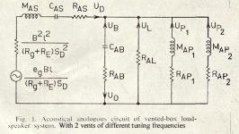
roddyama said:I took the liberty of adding another port arm to the Small’s equivalent circuit diagram of a BR type speaker. It becomes clear... that Up1 and Up2 are separate until they add acoustically to Up(total) at the upper-right node. Also since Map1 and Map2 are not mutually coupled, they are free to resonate at their own frequencies with their own losses, amplitudes, and phases. This make both Charles’ and Al’s cases logical. From there it’s a matter of manipulating the individual losses and port dimensions to arrive at a suitable combination for the total output required (Qptotal)..... I think this also answers Rolfy72’s questions as well.
Err, could you break that down just a teeny bit more for us non-engineers? Are you saying that when have two ports of different lengths, we end up with one tuning frequency, but the port output might have a peak that is broader than with a single port?
And could this be used to extend output lower than with a single port?
Hi Kelticwizard,kelticwizard said:
Err, could you break that down just a teeny bit more for us non-engineers? Are you saying that when have two ports of different lengths, we end up with one tuning frequency, but the port output might have a peak that is broader than with a single port?
And could this be used to extend output lower than with a single port?
Not quite. Each port has its own tuning frequency so will resonate at that frequency. So now you end up with two ports that resonate at different frequencies. When we talk about frequency response, we’re talking about the entire bandwidth of the speaker. Therefore, the contributions of both ports are included to provide output over a broader band. This is only when we are talking about response vs frequency or the frequency related effects.
In service, each port is going operate as a single port, and their outputs will add only when the resonances of both ports are being excited at the same time.
Rodd Yamashita
Thanks for clearing this up Rodd, it's always nice to have someone who knows the math and theory around
I really must start learning more of the hard theory side, rather than just relying on my experience and ears, but for someone with a degree in psychology it gets difficult
I really must start learning more of the hard theory side, rather than just relying on my experience and ears, but for someone with a degree in psychology it gets difficult
Rolfy72,
Of course there is the double chamber reflex box - which is a known way of tuning a reflex to 2 different frequencies.... don't ask me how though!
Taking that to the next level - no doubt you can have a triple, quadruple etc.... box (sort of like a constricted TL)
Dave.
Of course there is the double chamber reflex box - which is a known way of tuning a reflex to 2 different frequencies.... don't ask me how though!
Taking that to the next level - no doubt you can have a triple, quadruple etc.... box (sort of like a constricted TL
)Dave.
Dave Bullet said:Of course there is the double chamber reflex box - which is a known way of tuning a reflex to 2 different frequencies.... don't ask me how though!
For a thread on double chamber reflex boxes, complete with formulas and illustrations, see the following thread:
http://www.diyaudio.com/forums/showthread.php?threadid=3699&perpage=15&pagenumber=1
Thanks Al. Certainly it’s theory, although you have experimented with it and seemed to get some supporting results.
Math,
 Theory, Humm, un lezt zee,
 Zsychology? Is that like a story about Pablo’s dogs?
Lawriebuck, All,
This is certainly not the last word in port design. I’m still thinking on this one as some things just don’t set quite right yet.
Rodd Yamashita
Math,
Theory, Humm, un lezt zee, Zsychology? Is that like a story about Pablo’s dogs? Lawriebuck, All,
This is certainly not the last word in port design. I’m still thinking on this one as some things just don’t set quite right yet.
Rodd Yamashita
Thanks fella's, I thought that someone would've tried dual/varied lenght ports before!
So its not really not worth trying then?(plus I have no method of measurement or understanding...yet!)
And yup I've heard of the dual chamber with a port inbetween(sorta like a dual bandpass eh?) I've never heard any yet
So its not really not worth trying then?(plus I have no method of measurement or understanding...yet!)
And yup I've heard of the dual chamber with a port inbetween(sorta like a dual bandpass eh?) I've never heard any yet
- Status
- This old topic is closed. If you want to reopen this topic, contact a moderator using the "Report Post" button.
- Home
- Loudspeakers
- Multi-Way
- silly ? on port's