Many crossovers in published designs use compensation networks to flatten overall network impedance: typical is a LCR network placed directly across the input terminals to flatten the (often) rising impedance at crossover point.
This is supposed to make a more friendly amplifier load.
How important is this? Any opinions or experiences?
EspenE
This is supposed to make a more friendly amplifier load.
How important is this? Any opinions or experiences?
EspenE
I use low output impedance amps, so it's not an issue for me for that reason. However, Zobels and conjugate networks also help the crossover sections.
For a simplified example, a midrange speaker will have an inductor and a capacitor in series to set the upper and lower rolloffs. At low frequencies, the capacitor will increase in impedance, and the loss is the ratio of that impedance to the driver's impedance. But without a conjugate, there will be an impedance peak at the mid's low frequency resonance, and the loss from the input capacitor at that frequency will be much less than it should be. A similar issue occurs at the high end, especially for drivers with a strongly rising high frequency impedance from voice coil inductance.
For a simplified example, a midrange speaker will have an inductor and a capacitor in series to set the upper and lower rolloffs. At low frequencies, the capacitor will increase in impedance, and the loss is the ratio of that impedance to the driver's impedance. But without a conjugate, there will be an impedance peak at the mid's low frequency resonance, and the loss from the input capacitor at that frequency will be much less than it should be. A similar issue occurs at the high end, especially for drivers with a strongly rising high frequency impedance from voice coil inductance.
Curmudgeon said:I use low output impedance amps, so it's not an issue for me for that reason. However, Zobels and conjugate networks also help the crossover sections.
True, but a slightly different question. If one wants to use passive filters "off the shelf" they typically behave better if the load is purely resistive. some filters will, however, present a non-resistive load to the amplifier, even if the drivers are replaced with perfect resistors.
Thanks for the answers.
Yes, I'm aware of the use of zobel/conjugate network inside crossovers. What I'm after, is the use of compensation network "ouside" the actual crossover.
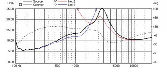
Consider the impedance curve attached: a network without impedance compensation with a broad impedance peak of 25 ohm at about 2500 Hz.
The same network with a LCR network of 10 ohm / 33 uF / 0,12 mH directly across the input gives flat impedance 5-8 ohm throughout.
On paper, the compensated network of course looks the best.
But does it matter in practice?
Only when amplifier output impedance is high?
How "high"?
Tube-amplifier-high?
Thanks,
Espen
Yes, I'm aware of the use of zobel/conjugate network inside crossovers. What I'm after, is the use of compensation network "ouside" the actual crossover.
Consider the impedance curve attached: a network without impedance compensation with a broad impedance peak of 25 ohm at about 2500 Hz.
The same network with a LCR network of 10 ohm / 33 uF / 0,12 mH directly across the input gives flat impedance 5-8 ohm throughout.
On paper, the compensated network of course looks the best.
But does it matter in practice?
Only when amplifier output impedance is high?
How "high"?
Tube-amplifier-high?
Thanks,
Espen
Attachments
o. With low amplifier output impedance, (high damping factor) and low cable resistance, I certainly agree that there would not be an effect.
If the amp and cable have a combined resistance of 1 ohm, a 5 ohm load will have about a 0.8 dB loss, and essentially zero into the 25 ohm load, resulting in about a 0.8 dB error. I'd consider that a second order effect, but if the speaker has a peak in that region you might not want the addition.
I hope I'm more helpful this time")
If the amp and cable have a combined resistance of 1 ohm, a 5 ohm load will have about a 0.8 dB loss, and essentially zero into the 25 ohm load, resulting in about a 0.8 dB error. I'd consider that a second order effect, but if the speaker has a peak in that region you might not want the addition.
I hope I'm more helpful this time
Hi,
The strange thing that people use these to make the speaker " valve friendly ".
IMO anything but. Valve amplifiers love high impedance. What needs
to be done is balancing the speakers response with a significant
source resistance - this is the genuine "valve friendly" speaker.
/sreten.
The strange thing that people use these to make the speaker " valve friendly ".
IMO anything but. Valve amplifiers love high impedance. What needs
to be done is balancing the speakers response with a significant
source resistance - this is the genuine "valve friendly" speaker.
/sreten.- Status
- This old topic is closed. If you want to reopen this topic, contact a moderator using the "Report Post" button.
- Home
- Loudspeakers
- Multi-Way
- Impedance compensation in crossovers