Alan,
Your input is much appreciated.
I'm away for the next week - so no progress here I'm afraid.
Hopefully I'll be able to get you the nominal R values for the drivers and the ESR values for the capacitors before too long.
You certainly seem to know your stuff. It seems like designers back then (as now I'd guess) had to deal with non-ideal "real" components, and compensate accordingly - leading to the fine art of compromise and design trade offs.
Given your obvious knowledge on this matter, may I ask what your background is? I'm curious.
Thanks in advance.
Grahame
Hello you 2, looks like summer is taking our time away from this project somewhat, mine is certainly limited.
I just wanted to say the felt test is still pending, the speakers metal grill is posing a small problem.....
Im going to try mounting it to the grill instead, will report later next week.
Pete / ToneDef2
Grahame are you going to be able to get the measurements Alan needs?
")
I just wanted to say the felt test is still pending, the speakers metal grill is posing a small problem.....
Im going to try mounting it to the grill instead, will report later next week.
Pete / ToneDef2
Grahame are you going to be able to get the measurements Alan needs?
Finally I'm back !
I am honoured that you ask !
Originally Mathematics and Physics, and later some Engineering of primarily Mechanical and Electrical/Electronic, but I don't practice such as a Career because it gets too tedious if done all the time.
I've was fascinated by speaker drivers for many years ago, thus applied my knowledge, and hopefully learning ability, to understanding how such function, and then combined with my love of music but small disposable Income, I learnt more so that I could become primarily DIY for my audio interests, but I do not know everything, and still have to acquire some more knowledge and think carefully about how to apply it before I can be more-so DIY for audio .
I hope you tried a simple test, such as a rolled up woollen sock stuck temporarily under the top lip of the cabinet, to hear the degree any audible benefit before you go to the trouble of a more difficult permanent mounting .
____________________________________________________
I'll post some replies to the remainder of your questions as soon as time is available Grahame.
regards,
Grahame said:
Alan,
Given your obvious knowledge on this matter, may I ask what your background is? I'm curious.
I am honoured that you ask !
Originally Mathematics and Physics, and later some Engineering of primarily Mechanical and Electrical/Electronic, but I don't practice such as a Career because it gets too tedious if done all the time.
I've was fascinated by speaker drivers for many years ago, thus applied my knowledge, and hopefully learning ability, to understanding how such function, and then combined with my love of music but small disposable Income, I learnt more so that I could become primarily DIY for my audio interests, but I do not know everything, and still have to acquire some more knowledge and think carefully about how to apply it before I can be more-so DIY for audio .
tonedef2 said:
the felt test is still pending, the speakers metal grill is posing a small problem.....
Im going to try mounting it to the grill instead, will report later next week.
I hope you tried a simple test, such as a rolled up woollen sock stuck temporarily under the top lip of the cabinet, to hear the degree any audible benefit before you go to the trouble of a more difficult permanent mounting .
____________________________________________________
I'll post some replies to the remainder of your questions as soon as time is available Grahame.
regards,
Hello,
Yes Alan i will do that first, my thoughts where since this is a potential defraction problem and it could not be seen with the grills on or off, it may just be a win win or draw ;-).
I will pick up more felt this weekend.
Recieved your email....wow....I will take a close look at those solder points and get back to you.
Pete / ToneDef2
doing the frequency response tests ...
You can measure the frequency response of the 66 as connected to the x-over, though the result you will get will be influenced by the acoustic of the environment you are measuring in, thus you may have to measure fairly closely to the speaker to get predominantly the direct sound from the drivers and less of what-ever reflected sound back from the room, or ground if you are measuring out-of -doors, and what-ever other noises are in the background.
If the measuring system has a Gate you can set it to close before the later arriving sounds and thus not contaminate your results with anything further delayed in time than the original direct sound from the loudspeaker.
Depending on options of gate closing time, you may need to raise the loudspeaker somewhat above the floor, and/or put a thick layer of sound absorbtive material on the floor halfway between the front of the speaker and the microphone to absorb at least the midrange and whatever treble is reflected from the floor to the mic.
Don't worry too much about trying to measure the bass response accurately - that is very difficult to do, except in a large absorbtive chamber or with the speaker on top of a mast more than 20 feet above the ground.
Another method is to measure with the speaker lying on its back in a shallow rectangular hole which is filled in around the cabinet to be flat ground level with the plane of the front panel.
One has to make a correction for the bass response with such measurement, but that is not a problem to estimate.
Even if not buried to depth of front panel, a flat on back outside and well away from all other reflecting surfaces can give fairly accurate midrange and treble response, as those frequencies are more directional.
However you place the loudspeaker, ensure it cannot wobble, as the frequencies of any wobbles will contaminate the measurement result.
Try a 3-points support under the speaker, well spaced apart - such will minimise wobble.
4 or more points is not as reliable as 3.
If you measure too close to the speaker you will not get the actual response of the drivers added together in the way they would be heard, thus measure at the standard 1 metre in front of the cabinet.
You will get a different response in part depending on the vertical axis you measure on, thus try first measuring with the mic. directly on the MD 500's axis, as that was the standard axis then for flattest response from 3-way loudspeakers.
Try measurements also with mic. directly on the HF 2000 axis, and next from a height with the mic. at the halfway point between tweeter and mid-dome.
These results will show you the best listening axis as you will see the interference effects between the drivers, and hopefully less from one of those positions.
Vertical axis measurements are often done from 6 feet, or 2 meters, distance, because that is a distance more like a typical listening distance, thus if you can set a Gate time to accept that distance -{in time its just under 6 milli-seconds}- and then close before the arrival of the floor reflection, then try that distance for each of the 3 vertical axis heights.
Measure the other 66, at least from the mic. position that gave the flattest freq. resp. , to check its drivers are similar to the first 66s'.
For measuring the individual drivers separately:-
You will see on the frequency response plots for the drivers I posted Links to Manufacturers of, that the measurements are from a frequency substantially lower than the driver's response bandwidth, and extend to frequencies higher than the driver's bandwidth.
These measurements are done at low power, thus no damage to the tweeters and mid-domes when feeding them signal at lower frequencies than their Fs.
For example, set the out-put of the driving amplifier to 2 volts with a frequency in the middle of the driver's bandwidth, and with the driver connected directly -{no cross-over in circuit}.
Sweep down in frequency and listen carefully.
If you hear buzzing or distortion then you will be driving it too hard at or below its resonant frequency.
Make a note of the frequency you began to hear any such noise at for both the MD 500 and the HF 2000.
You can then re-set the amp. to lower output if necessary, eg: 1 volt at the offending frequency.
To have useful information about both the MD 500 and the HF 2000 each should be measured from a frequency at least one Octave below each's Fs.
I think the MD 500 will be close to its Fs at 500 Hz, thus for it try a measurement starting from 1 octave below the cross-over point, 500 Hz, therefore start from 250 Hz.
If it is sounding OK at 250 Hz with 2 volts drive, you can start the sweep up from a lower frequency if you wish, but no need to start any lower than 2 octaves below -which is 125 Hz.
For the HF 2000 it would be useful to have from 2 octaves below the cross-over frequency if possible, thus start sweep up from 1.25 kHz with 2 volts drive if no audible distress.
Note : 2 volts drive of a single frequency, especially of midrange and treble frequencies can be quite distubing to listen to !
Sweep up to as high in frequency as posible for the MD 500, as its useful to know what its roll-off looks like, thus to at least 10 kHz, though a bit higher would be useful if one was later considering an alternate tweeter to work with it.
For the Active bass driver -{forget the passive radiator, though yes, its output will add to that of the active driver at low frequencies, but as I said above, such frequencies will be difficult to measure accurately, and we don't need them measured for this cross-over project}-
start the sweep from as low in frequency as you like, though from 125 Hz will be sufficient, and even if you can only get useable results from 250 Hz and above, that is at least from 1 octave below the cross-over point.
It would be useful to know how the bass driver behaves well above the x to the mid - see the response of that Celestion 12" I posted about - as the 12" in the 66 likely does misbehave somewhat in its midrange and possibly in the low treble - perhaps even as high as the 5 kHz cross-over point - as Celestion have used the steep 4th order filter on it.
But, if your measuring equipment is a type where Resolution is reduced when Bandwidth is increased, then measure the bass driver up to at least 1 octave above x -{1 kHz}- and preferably to 2 octaves above -{2 kHZ}.
If you can do that with high resolution, you can next do a plot starting at 500 Hz and measure at high resolution to what-ever frequency in the low treble is possible with such equipment restriction.
If possible, measure all 3 drivers with the same drive voltage, whether 2 volts or 1 volt or whatever, because if your equipment has an accurate scale for the results we will the know if any relative differences in sensitivity/efficiency between the drivers -{there will be at least a little, particually wrt the bass driver}.
This information will be useful when the old electrolytic caps with their high ESRs are changed to modern caps with negligible ESRs, because the original ESRs are likely part or the Impedance taken into account for each x-over filter, and the ESRs do reduce the output of the drivers with at least the series connected caps, thus I think small value resistors may have to be added to new caps to simulate the original ESR magnitudes - at least for C6 and probably for C5 - I will post more about such in a later post.
Measuring individual drivers connected to the cross-over when the other 2 drivers are not connected to the cross-over is difficult and potentially dangerous for the output stage of the driving amplifier, thus if you want to see the effect the cross-over filters have on each driver individually -{and such would be useful}- then you will have to connect resistors in the places where drivers have been disconnected.
Use a resistor of value about 20% larger than the DC resistance of the driver, as such is close to the likely mid-band impedance of the driver. This will give useable results, though not completely accurate for frequencies where the missing drivers' impedances are rising - see those Impedance plots on the web-sites I posted links to.
Thus for your MD 500s of 6.7 and 6.9 ohms, substitute with an 8.2 ohm resistor.
What are the DC ohms for the bass drivers and the HF 2000s ?
A simple cheap 5 watt wirewound resistor is sufficient.
It does not need to be non-inductive, because the driver it is substituting for is itself inductive !
Is there anything relevant to any of the above in the Manuals for your test equipment ?
Grahame said:
Alan - are there any issues I should be aware of when running the frequency response tests - I think it runs sweep tones / impulses via the inputs - 20-20KHz - I think - so that should be OK with the crossover in place.
If I run the sweeps directly to the drivers without the crossovers ( if I can wire it up like that) should I restrict the frequency range I subject each of the drivers to?
e.g. MD 500 says .5-5KHz on back
so I'd guess 20-500 for the sub
500-5KHz for the MD500
5KHz - 20KHz for the HF2000's
I won't try anything until I hear from you and have read the manuals on the measurement gear.
You can measure the frequency response of the 66 as connected to the x-over, though the result you will get will be influenced by the acoustic of the environment you are measuring in, thus you may have to measure fairly closely to the speaker to get predominantly the direct sound from the drivers and less of what-ever reflected sound back from the room, or ground if you are measuring out-of -doors, and what-ever other noises are in the background.
If the measuring system has a Gate you can set it to close before the later arriving sounds and thus not contaminate your results with anything further delayed in time than the original direct sound from the loudspeaker.
Depending on options of gate closing time, you may need to raise the loudspeaker somewhat above the floor, and/or put a thick layer of sound absorbtive material on the floor halfway between the front of the speaker and the microphone to absorb at least the midrange and whatever treble is reflected from the floor to the mic.
Don't worry too much about trying to measure the bass response accurately - that is very difficult to do, except in a large absorbtive chamber or with the speaker on top of a mast more than 20 feet above the ground.
Another method is to measure with the speaker lying on its back in a shallow rectangular hole which is filled in around the cabinet to be flat ground level with the plane of the front panel.
One has to make a correction for the bass response with such measurement, but that is not a problem to estimate.
Even if not buried to depth of front panel, a flat on back outside and well away from all other reflecting surfaces can give fairly accurate midrange and treble response, as those frequencies are more directional.
However you place the loudspeaker, ensure it cannot wobble, as the frequencies of any wobbles will contaminate the measurement result.
Try a 3-points support under the speaker, well spaced apart - such will minimise wobble.
4 or more points is not as reliable as 3.
If you measure too close to the speaker you will not get the actual response of the drivers added together in the way they would be heard, thus measure at the standard 1 metre in front of the cabinet.
You will get a different response in part depending on the vertical axis you measure on, thus try first measuring with the mic. directly on the MD 500's axis, as that was the standard axis then for flattest response from 3-way loudspeakers.
Try measurements also with mic. directly on the HF 2000 axis, and next from a height with the mic. at the halfway point between tweeter and mid-dome.
These results will show you the best listening axis as you will see the interference effects between the drivers, and hopefully less from one of those positions.
Vertical axis measurements are often done from 6 feet, or 2 meters, distance, because that is a distance more like a typical listening distance, thus if you can set a Gate time to accept that distance -{in time its just under 6 milli-seconds}- and then close before the arrival of the floor reflection, then try that distance for each of the 3 vertical axis heights.
Measure the other 66, at least from the mic. position that gave the flattest freq. resp. , to check its drivers are similar to the first 66s'.
For measuring the individual drivers separately:-
You will see on the frequency response plots for the drivers I posted Links to Manufacturers of, that the measurements are from a frequency substantially lower than the driver's response bandwidth, and extend to frequencies higher than the driver's bandwidth.
These measurements are done at low power, thus no damage to the tweeters and mid-domes when feeding them signal at lower frequencies than their Fs.
For example, set the out-put of the driving amplifier to 2 volts with a frequency in the middle of the driver's bandwidth, and with the driver connected directly -{no cross-over in circuit}.
Sweep down in frequency and listen carefully.
If you hear buzzing or distortion then you will be driving it too hard at or below its resonant frequency.
Make a note of the frequency you began to hear any such noise at for both the MD 500 and the HF 2000.
You can then re-set the amp. to lower output if necessary, eg: 1 volt at the offending frequency.
To have useful information about both the MD 500 and the HF 2000 each should be measured from a frequency at least one Octave below each's Fs.
I think the MD 500 will be close to its Fs at 500 Hz, thus for it try a measurement starting from 1 octave below the cross-over point, 500 Hz, therefore start from 250 Hz.
If it is sounding OK at 250 Hz with 2 volts drive, you can start the sweep up from a lower frequency if you wish, but no need to start any lower than 2 octaves below -which is 125 Hz.
For the HF 2000 it would be useful to have from 2 octaves below the cross-over frequency if possible, thus start sweep up from 1.25 kHz with 2 volts drive if no audible distress.
Note : 2 volts drive of a single frequency, especially of midrange and treble frequencies can be quite distubing to listen to !
Sweep up to as high in frequency as posible for the MD 500, as its useful to know what its roll-off looks like, thus to at least 10 kHz, though a bit higher would be useful if one was later considering an alternate tweeter to work with it.
For the Active bass driver -{forget the passive radiator, though yes, its output will add to that of the active driver at low frequencies, but as I said above, such frequencies will be difficult to measure accurately, and we don't need them measured for this cross-over project}-
start the sweep from as low in frequency as you like, though from 125 Hz will be sufficient, and even if you can only get useable results from 250 Hz and above, that is at least from 1 octave below the cross-over point.
It would be useful to know how the bass driver behaves well above the x to the mid - see the response of that Celestion 12" I posted about - as the 12" in the 66 likely does misbehave somewhat in its midrange and possibly in the low treble - perhaps even as high as the 5 kHz cross-over point - as Celestion have used the steep 4th order filter on it.
But, if your measuring equipment is a type where Resolution is reduced when Bandwidth is increased, then measure the bass driver up to at least 1 octave above x -{1 kHz}- and preferably to 2 octaves above -{2 kHZ}.
If you can do that with high resolution, you can next do a plot starting at 500 Hz and measure at high resolution to what-ever frequency in the low treble is possible with such equipment restriction.
If possible, measure all 3 drivers with the same drive voltage, whether 2 volts or 1 volt or whatever, because if your equipment has an accurate scale for the results we will the know if any relative differences in sensitivity/efficiency between the drivers -{there will be at least a little, particually wrt the bass driver}.
This information will be useful when the old electrolytic caps with their high ESRs are changed to modern caps with negligible ESRs, because the original ESRs are likely part or the Impedance taken into account for each x-over filter, and the ESRs do reduce the output of the drivers with at least the series connected caps, thus I think small value resistors may have to be added to new caps to simulate the original ESR magnitudes - at least for C6 and probably for C5 - I will post more about such in a later post.
Measuring individual drivers connected to the cross-over when the other 2 drivers are not connected to the cross-over is difficult and potentially dangerous for the output stage of the driving amplifier, thus if you want to see the effect the cross-over filters have on each driver individually -{and such would be useful}- then you will have to connect resistors in the places where drivers have been disconnected.
Use a resistor of value about 20% larger than the DC resistance of the driver, as such is close to the likely mid-band impedance of the driver. This will give useable results, though not completely accurate for frequencies where the missing drivers' impedances are rising - see those Impedance plots on the web-sites I posted links to.
Thus for your MD 500s of 6.7 and 6.9 ohms, substitute with an 8.2 ohm resistor.
What are the DC ohms for the bass drivers and the HF 2000s ?
A simple cheap 5 watt wirewound resistor is sufficient.
It does not need to be non-inductive, because the driver it is substituting for is itself inductive !
Is there anything relevant to any of the above in the Manuals for your test equipment ?
Possible MD 500 Source?
Hi everyone,
I am just going to jump in here (I have to admit I haven't read much of the thread)..
I have always wondered if the dome mid of a Bang & Olufsen Beovox 5700 is the same as used in the 66. Anyone know? Certainly by eye they look the same.
I have seen these go on ebay for ~ £60 a working pair (maybe they sound good and are worth keeping intact?)
Here's a photo:
Attachments
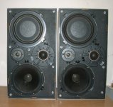
B & O's dome-mid and Celestion's .
Hi NAT , there is mention of one Bang & Olufsen model loudspeaker and its mid-dome in a post in one of the Threads about Celestion 66 in this Forum - a thread that you will find my name and tonedef2 in.
I have forgotten which of 3 threads some-one posted about it in, how-ever the particular B&O dome-mid identified there was apparently made by Celestion for B&O, and is a lower powered version of the MD500.
No other specifications for it were posted, then - I don't know if any-one has added since, but try a Search for, with our names and look at Threads we posted in a few months ago.
The tweeter in your photo of the B&O looks like a Celestion made, as also does the Passive Radiator, thus possibly also is the woofer.
My memory !
Umm , Nat, the thread with the info is actually this one - my memory !
Look on page 4 of this thread at Post #33 by Greg3333.
The two other active drivers in the 5700 are a bit rough looking for Celestion models, unless they were made at cheaper price for manufacturers who do not expect their customers will take off the grille cloths and look at the drivers - such as B&O whose customers tend to look at the finished item presented as attractive with grille cloth on.
The woofer could be from a European manufacturer of that era such as Philips then made in Holland, or quite possibly from SEAS in Norway, as may be the tweeter if its not a cheaper Celestion model.
Have a look at this page i spotted........bye for now, taking the boat out.
http://www.users.bigpond.com/kfleming/bigspeakers.htm
Pete
http://www.users.bigpond.com/kfleming/bigspeakers.htm
Pete
Here are some pics from a recent Beovox 5700 sale on ebay. It's very similar to the Ditton 66.
http://cgi.ebay.com/Vintage-Bang-Ol...ryZ14993QQssPageNameZWDVWQQrdZ1QQcmdZViewItem
*********************
I've been following this thread and want to thank all of you for sharing your expertise here. I have 2 pairs of Ditton 66's, and the attention that that speaker is getting here has only increased my fondness for it.
My speakers seem to be running okay....but then I really don't know what a pristine 66 should sound like.
Should I assume that by now, after about 35 years, that the crossovers no longer meet specs....and that they need to be refurbished?
Or might they still be fine?
Thanks
Hi sba,
thanks for posting the link to the pics on ebay, they look the same version of the 5700 model as in post #66 of this thread, but a larger pic we can see more clearly !
Final bid price was a lot of money for old speakers that will most likely need some reconditioning work, and perhaps a lot of work.
If your 66s sound OK and don't have any of the buzzing sound in their mid-domes, that tonedef2 explained about -{I think in this thread, though there are two other, much shorter threads about Ditton 66s that he and I have posted a bit in also}- then you will only have to check the cross-overs.
The inductors will probably be OK, but the capacitors could be leaking in part, and may have drifted too far in value from their original spec. value.
See posts #30 and #38 on page 2 of this thread for what I wrote about the capacitors, then follow-up with what I have written on page 3.
I will be posting more about replacement capacitors soon, thus you may like to follow that and buy the caps and E.S.R. simulating resistors and install these yourself, then hear what your 66s sound like.
Do one pair first, and compare the sound to the older parts sound of the other pair.
Thus, do keep looking here for what we may discuss next.
best wishes,
tonedef2 said:Have a look at this page i spotted........bye for now, taking the boat out.
Pete
Hi Pete, great pic. ! Its almost unbelieveable what some enthusiasts have tried over the years, and I wish I'd heard those monsters in action !!
I hope you had a good venture, or an adventure ? , out in your boat !
partial error in my post #56
It is so long since I worked with electrolytic caps in a wide-band audio-critical application that it slipped my mind that the ESR,
{which is dependant on the Dissipation Factor of the dielectric}, varies with frequency !
Basically, dissipation factor in electrolytic caps is higher at low frequencies and lower at high frequencies, BUT, do not confuse that with the Capacitive Reactance, which is of course higher at low frequencies and lower at high frequencies.
Dissipation Factor represents a loss, it is not useful, and it does not have the same phase angle in circuit as capacitive reactance, thus we cannot allow for it by simply increasing the value of capacitor when we substitute with a low dissipation factor plastic film cap.
Thus we have a different ESR at 500 Hz in the 24uF cap than is at 5 kHz !
So, how to simulate that with a fixed resistor, to try to keep the Impedance at what it is at 500 Hz region and 5 kHz region ?
Well, it can't be done simply, thus one has to compromise and select an in-between value, put it in and listen, and if not liking the sound then either slightly increase or slightly decrease the resistance value, but I hope if I estimate close enough, and am lucky, then you may not want to change the resistors !
The ESR in the 72uF caps will probably be about 1 ohm at 500 Hz, possibly a little less and hopefully not much greater.
The ESR in the 4uF black cap will probably be about 1 ohm, or slightly less, at 5 kHz.
ESR at 500 Hz is not relevant for the 4uF cap.
The 24uF cap is in Series with the mid-dome and both sections of the x-over filter, thus its ESR is relevant in the regions around both x-over frequencies.
At 500 Hz it could be about 2.5 ohm or slightly larger, and at 5 kHz it will be quite low, probably less than 0.2 ohm.
I recommend using no less than 1.5 ohm for the resistor, because less will shift the lower x-over point up a bit too much.
1.5 ohm will have minimal effect on the higher x-over frequency, but you might notice slightly less upper midrange brightness. If that is audibly not wanted, then reduce resistor to 1 ohm or 0.5 ohm, and yes that will have shifted the lower cut-off up a little, but will be part compensated by being a little bit louder at the low end of the mid-dome's output, for about an octave, approx. 600 - 1200 Hz.
As I said, this will involve a compromise, a trade-off, but probably not an excessive one.
Polypropylene caps have almost negligible ESR, as their dissipation factor is very low.
Thus we add a series resistor to each polyprop. cap to simulate the ESR of the electro's so the impedances, including the phase angles, will be the same as Celestion's original, so that the drivers will cross over at the original design frequencies.
So, why not simply use new electrolytic caps which have the higher ESRs ?
Well, electrolytic caps also have high Dielectric Absorbsion.
What is that ?
It is a Memory effect. Basically when the electro cap is charged by the signal {music} it retains part of that charge and does not fully discharge and charge to the opposite polarity when the signal changes polarity.
It does charge and discharge and re-charge etc, but always lagging the signal by a much larger time interval than the Time Constant of the circuit.
The audible consequence is a muddying of the music owing to the mixing of delayed release information being added to new information.
{this is a simplification of the full process, but it's sufficient to give you the idea}
Polypropylene caps have very very low dielectric absorbsion. That is one reason why they are so good for audio signal use.
I write too much !
Now I have not enough time remaining to post about the brands of polyprop. caps which you both asked about a long time ago, and recommend sizes and values, etc ...
I am sorry. I will try to do that next time.
alan-1-b said:
The E.S.R. values of the electrolytic capacitors will be significant also, and likely need duplicating when replacing with the much lower ESR polypropylene capacitors, especially for the 72uF cap that is in direct parallel with the woofer, and perhaps for the other 72uF, and less likely for the 24uF -{which will have a lower ESR anyway}, and highly unlikely to be necessary for the 4uF black cap. <-- UP-DATE following this -->
I've changed my mind after thinking about an audible effect that tonedef2 described earlier. Now I think there may be need to add the resistance here to reduce to negligible level a possible audible resonance that a very low ESR cap could cause to occur here, as it seems it may be with the low ESR cap later put in his x-overs instead of the black 4uF electrolytic.
E.S.R. = Equivalent Series Resistance
,
It is so long since I worked with electrolytic caps in a wide-band audio-critical application that it slipped my mind that the ESR,
{which is dependant on the Dissipation Factor of the dielectric}, varies with frequency !
Basically, dissipation factor in electrolytic caps is higher at low frequencies and lower at high frequencies, BUT, do not confuse that with the Capacitive Reactance, which is of course higher at low frequencies and lower at high frequencies.
Dissipation Factor represents a loss, it is not useful, and it does not have the same phase angle in circuit as capacitive reactance, thus we cannot allow for it by simply increasing the value of capacitor when we substitute with a low dissipation factor plastic film cap.
Thus we have a different ESR at 500 Hz in the 24uF cap than is at 5 kHz !
So, how to simulate that with a fixed resistor, to try to keep the Impedance at what it is at 500 Hz region and 5 kHz region ?
Well, it can't be done simply, thus one has to compromise and select an in-between value, put it in and listen, and if not liking the sound then either slightly increase or slightly decrease the resistance value, but I hope if I estimate close enough, and am lucky, then you may not want to change the resistors !
The ESR in the 72uF caps will probably be about 1 ohm at 500 Hz, possibly a little less and hopefully not much greater.
The ESR in the 4uF black cap will probably be about 1 ohm, or slightly less, at 5 kHz.
ESR at 500 Hz is not relevant for the 4uF cap.
The 24uF cap is in Series with the mid-dome and both sections of the x-over filter, thus its ESR is relevant in the regions around both x-over frequencies.
At 500 Hz it could be about 2.5 ohm or slightly larger, and at 5 kHz it will be quite low, probably less than 0.2 ohm.
I recommend using no less than 1.5 ohm for the resistor, because less will shift the lower x-over point up a bit too much.
1.5 ohm will have minimal effect on the higher x-over frequency, but you might notice slightly less upper midrange brightness. If that is audibly not wanted, then reduce resistor to 1 ohm or 0.5 ohm, and yes that will have shifted the lower cut-off up a little, but will be part compensated by being a little bit louder at the low end of the mid-dome's output, for about an octave, approx. 600 - 1200 Hz.
As I said, this will involve a compromise, a trade-off, but probably not an excessive one.
Polypropylene caps have almost negligible ESR, as their dissipation factor is very low.
Thus we add a series resistor to each polyprop. cap to simulate the ESR of the electro's so the impedances, including the phase angles, will be the same as Celestion's original, so that the drivers will cross over at the original design frequencies.
So, why not simply use new electrolytic caps which have the higher ESRs ?
Well, electrolytic caps also have high Dielectric Absorbsion.
What is that ?
It is a Memory effect. Basically when the electro cap is charged by the signal {music} it retains part of that charge and does not fully discharge and charge to the opposite polarity when the signal changes polarity.
It does charge and discharge and re-charge etc, but always lagging the signal by a much larger time interval than the Time Constant of the circuit.
The audible consequence is a muddying of the music owing to the mixing of delayed release information being added to new information.
{this is a simplification of the full process, but it's sufficient to give you the idea}
Polypropylene caps have very very low dielectric absorbsion. That is one reason why they are so good for audio signal use.
I write too much !
Now I have not enough time remaining to post about the brands of polyprop. caps which you both asked about a long time ago, and recommend sizes and values, etc ...
I am sorry. I will try to do that next time.
Hello all,
Allen you are the man! And have no reason to say sorry, your help with this project has been amazing, rather there would be no project without you! I will speak for us all and say thank you very much in bring our 66's / joy of music back.
Im looking for one orig 66 version 2 xover board to hack up for this next phase of our project......
News> I finished messing around with the diffraction problem> net result was, attaching the audio wool to the upper grill works best and did have a good affect, I will describe as less blurring of the high freq energy, note: if you listen with grills off........then I simply used a custom cut wool with very little Velcro to slip under the top over hang (your grill will fit a little tighter), works great and am now working on the aesthetics.....
Hello sba!
1-Did Graham ever get you the remaining measurements?
2-I will post some picks of the grill soon for analysis as im pretty sure as the audio wool loosens over time we have a ringing affect at moderate attenuation.
Pete / ToneDef2
Hi Pete,
No Grahame hasn't sent me anything, nor posted recently.
When-ever you happen to open your 66s next, if you could measure the DC resistances of the woofers such may be helpful.
I think they will be nominally 4 ohm, thus expect to see about 3.3 ohms on your meter, if your meter is suffciently accurate at measuring low resistance values.
Grahame measured his MD500s at 6.7 and 6.9 ohms, if I'm remembering correctly, and that is posted somewhere here-back, but I've forgotten if the HF2000's DCRs are posted anywhere. {Yes I will scroll back and look} .
From the x-over components' values it seems the HF2000s are nominally 8 ohm, thus would measure about 6.7 ohm or so .
I'm more interested in the more time consuming Impedance measurements at the x-over frequencies and 1 octave each side of for each of the drivers, especially if we are to consider replacement tweeters later, to integrate such as well as possible with the MD500s, so we'll wait to see what Grahame may be able to come up with.
____________________________________________________
sba, if you are reading this, are you able to do Impedance measurements on drivers at midrange frequencies ?
I posted something about such earlier in this thread .
- Status
- This old topic is closed. If you want to reopen this topic, contact a moderator using the "Report Post" button.
- Home
- Loudspeakers
- Multi-Way
- Celestion 66 needs mid-range