pinkmouse said:Does anyone use this? It looks very powerful, but extremely unfriendly. Any tips?
http://www.akabak.de/Ak-English.htm
I got used to it after several days of trying around. Use the "exercises" pdf. Once you are through the parts you want to know, try to exchange stuff in the examples and see what happens. The program is best learned by trying around, using the main manual only as reference for the individual functions parameters. Akabak is very "logical". Once you understand how it works, it becomes easy to use and do new stuff. At least thats how it worked for me.
Very basically, every line of code is an element of the speaker, like a driver or a closed volume or a reflex port or whatever. It starts with the type of the element, then its parameters. They are connected by nodes which reflect the way the air flows through them.
Henkjan said:I took the liberty of making a PDF from Don's tutorial
Thank you. It's easier on the eyes than the original post.
If people find it useful and maybe suggest improvements, I'll add some pictures and diagrams for the next edition.
Regarding soongsc and Patrick's comments on simulating complex voumes, there is a good example in the main manual on modelling a bandpass box that is an odd shape, by using multiple duct sections.
Akabak is mostly a one-dimensional program, where the width or cross sectional area of a volume must be significantly smaller than the wavelengths being modelled. So you can model the waves bouncing back and forth in a long thin pipe, but not in a cube with sides as long as the pipe.
One way to model an irregular voume is to break it down into a series of cone segments and model each segment as a duct. The openings at each end of the cone segments do not have to be regular, they can be irregular shapes, so long as you know their cross-sectional areas. You just have to make the cone segments short enough so that their area changes more or less linearly from one opening to the next. (Or follow one of the built-in area laws for horns.) The more irregular your volume, the more cones you will need to break it up into. This is the same as in a CAD program, where the more irregular a shape is the more polygons you need to model it accurately.
(I've done quite a lot of CAD work myself, for example I digitised my house and its section (plot of land) to the nearest 1 cm and modelled it in a 3D CAD program, so that I could work out how best to renovate it and make additions.)
AkAbak Duct (port) end correction
Most reflex enclosure simulators specify the port length as a physical value - the length that a real port would be cut to in order to provide the same results as the simulator. Ports behave as though they are slightly longer than their physical lengths, because of the mass of the air just beyond their ends. The simulators add this effect, called "end correction", internally when simulating.
AkAbak does not always add port (Duct) end correction internally. The rules are as follows:
- For a Duct connected to a Duct (and some other elements), AkAbak does not internally add any end correction. The length value set on the Duct definition is thus the physical length. End correction(s) appropriate to the topology must be must be added to obtain the effective length for simulation. (Or, an air mass (AcouMass) can be used to join the Ducts.)
- For a Duct connected to an Enclosure, AkAbak internally adds a "baffle" end correction to that end when simulating. An end correction appropriate to the topology must be manually added at the other end.
- A Radiator element attached to the end of a Duct provides the correct radiation impedance, so no added end correction is required for that end.
- AkAbak's Helmholtz calculator dialog assumes you are simulating an Enclosure attached to a Duct. It internally adds a "baffle" correction to that end. An appropriate end correction has to be added to the other end for correct simulation. For a standard reflex enclosure simulation, this is provided by the Radiator attached to the Duct.
- For a vented Enclosure ("integrated port"), AkAbak adds "baffle" correction to the enclosure end of the port and a radiator to the other end. The port length specified on the Enclosure element definition is thus the physical length and no added end correction is required.
Where end correction is required, the following adjustments are suggested (AkAbak manual, page 181, "End Correction")
L+ = 0.425× duct diameter One end. Vent terminates in a baffle.
L+ = 0.306× duct diameter One end. Vent terminates freely.
For Duct joined to Duct, the required end correction depends on the ratio of the two duct sizes. It will vary from 0 (both Ducts the same size) to about 0.425x Duct diameter (one Duct much larger than the other).
Last edited:
For a vented Enclosure ("integrated port"), AkAbak adds "baffle" correction to the enclosure end of the port and a radiator to the other end. The port length specified on the Enclosure element definition is thus the physical length and no added end correction is required.
Hi Don,
I have been experimenting with the AkAbak enclosure element, but cannot get the same result for port output power as I get when using a duct plus inner end corrrection.
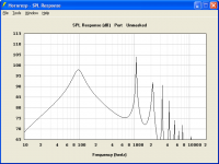
1. Hornresp_port.png shows the Hornresp result.
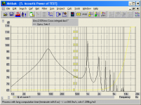
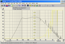
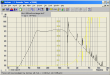
2. AkAbak-port1.png shows the AkAbak result using Hornresp exported data but with an inner end corrrection manually added to the AkAbak port duct element length.
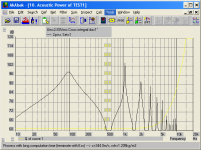
3. AkAbak_port2.png shows the AkAbak result using an enclosure element.
4. Test1.txt shows the script I am using to generate AkAbak_port2.png.
I am hoping that you might be able to see where I am going wrong
") .
.Thanks and kind regards,
David
Attachments
Hi David,
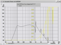
Well, that is odd... I opened AkAbak, new script, pasted in the script you provided, and got the attached result. It does not look like your second image.
I'll see if I can work out what's happening.
(EDIT) Port power, not combined power. Hmmm...
(EDIT 2) OK, my mistake. I was viewing the sum power, not just that of the port. Selecting just the enclosure label to plot (or setting "NoRad" on the Radiator) gives the same result as yours. Now I am "on the same page", I'll get back to your original question.
Attachments
Last edited:
OK, I see the reason.
For the Enclosure element, you need to specify the keyword "Long".
For a normal vented enclosure, AkAbak assumes that the driver and port are mounted on the same surface with no distance between them, and that the Enclosure Length parameter refers to the distance between the driver and the back wall of the enclosure. (Imagine the vent being mounted coaxially, coming through the centre of the driver.)
Specifying "Long" puts (Enclosure Length) distance between the vent and the driver. This is illustrated on page 171 of the AkAbak manual, figs 93 and 94.
This shows up a problem when simulating a vented enclosure using an Enclosure -> Duct -> Radiator. Specifying "Long" does not work, the parameter is ignored. Your method of using two Ducts allows the "length" of the enclosure to be included.
In real life, we're probably worrying too much. The simulation differences show up at frequencies where the one-dimensional model breaks down - where the wavelengths are no longer long compared to the element dimensions. Nevertheless, it reinforces the requirement to model as accurately as the bandwidth requires. I now see why you don't intend to change the AkAbak export model.
For reference, here is the model I used. It contains 3 systems:
1: The model you posted.
2: The same model with the vent modelled by a Duct instead of as part of the Enclosure.
3: Your original model as currently exported by Hornresp.
Select labels 1, 11, and 21 in Sum -> Acoustic Power...
Code:
|DATA EXPORTED FROM HORNRESP - RESONANCES NOT MASKED

|COMMENT: Bass-reflex speaker

|========================================================================================================

|REQUIRED AKABAK SETTINGS:

|File > Preferences > Physical system constants:

|Sound velocity c = 344m/s
|Medium density rho = 1.205kg/m3

|Sum > Acoustic power:

|Frequency range = 10Hz to 20kHz
|Points = 533
|Input voltage = 2.83V rms
|Integration = 2Pi-sr
|Integration steps = 1 degree ... 1 degree
|Integration method = Cross

|========================================================================================================

Def_Const |Hornresp Input Parameter Values
{
|Length, area and volume values converted to metres, square metres and cubic metres:

Vrc =    14.00e-3;  |Rear chamber volume (litres)
Lrc =    16.00e-2;  |Rear chamber average length (cm)
Arc =    875.0e-4;  |Rear chamber area (sq cm)

Ap  =    40.00e-4;  |Rear chamber port cross-sectional area (sq cm)
Fh  =    96.39e-0;  |Helmholtz resonance frequency (hertz)
Lpt =    6.191e-2;  |Length of port (cm)
Dpt =    3.568e-2;  |Diameter of port (cm)

}

Def_Driver 'Driver'

  Sd=350.00cm2
  Bl=18.00Tm
  Cms=4.00E-04m/N
  Rms=4.00Ns/m
  fs=51.6164Hz  |Mmd = 20.00g not recognised by AkAbak, fs calculated and used instead
  Le=1.00mH
  Re=6.00ohm
  ExpoLe=1

System 'Vented'
|========================================================================================================

|Network node numbers for this direct radiator vented-box system:

|       0-Voltage-1
|                 |
|Enclosure(1)-5-Driver-6-Radiator(2)

|========================================================================================================

  Driver Def='Driver''Driver'
    Node=1=0=5=6

  Enclosure 'Vented-box enclosure'
    Node=5
    Vb={Vrc}
    Lb={Lrc}
    fb={Fh}
    SD={Ap}
    Long
    Visc=0
    Label=1

  Radiator Def='Driver' 'Diaphragm'
    Node=6
    Label=2


System 'Ported'
|========================================================================================================

|Network node numbers for this direct radiator ported-box system:

|     0-Voltage-1
|               |
|Enclosure-15-Driver-16-Radiator(12)
|           |
|           +-Duct-17-Radiator(13)
|========================================================================================================

  Driver Def='Driver' 'Driver'
    Node=1=0=15=16

  Enclosure 'Ported enclosure'
    Node=15
    Vb={Vrc}
    Lb={Lrc}
    Long     |Ignored by AkAbak

  Radiator Def='Driver' 'Diaphragm'
    Node=16
    Label=12

  Duct    'Duct'
    Node=15=17
    SD={Ap}
    Len={Lpt}
    Visc=0

  Radiator Def='Duct' 'Port'
    Node=17
    Label=11


System 'Ducted'
|========================================================================================================

|Network node numbers for this direct radiator ducted-box system:

|                        0-Voltage-1
|                                  |
|Radiator(21)-23-Port-24-Duct-25-Driver-26-Radiator(22)

|========================================================================================================


  Driver Def='Driver' 'Driver'
    Node=1=0=25=26

  Duct 'Rear chamber'
    Node=25=24
    SD={Arc}
    Len={Lrc}
    Visc=0

  Radiator Def='Driver' 'Diaphragm'
    Node=26
    Label=22

  Duct 'Port'
    Node=24=23
    SD={Ap}
    Len={Lpt}
    Visc=0

  Radiator Def='Port' 'Port outlet'
    Node=23
Label=21Hi Don,
I tried that earlier myself, but for some reason it didn't make any difference - I must have put it in the wrong place initially.
Many thanks for clearing up the mystery for me!
For those systems having enclosure and port dimensions that meet the Hornresp "Helmholtz Resonator" constraints, I was thinking of exporting the AkAbak script as attached. What do you think, would this be okay?
Kind regards,
David
For the Enclosure element, you need to specify the keyword "Long".
I tried that earlier myself, but for some reason it didn't make any difference - I must have put it in the wrong place initially
.Many thanks for clearing up the mystery for me!
I now see why you don't intend to change the AkAbak export model.
For those systems having enclosure and port dimensions that meet the Hornresp "Helmholtz Resonator" constraints, I was thinking of exporting the AkAbak script as attached. What do you think, would this be okay?
Kind regards,
David
Attachments
... For those systems having enclosure and port dimensions that meet the Hornresp "Helmholtz Resonator" constraints, I was thinking of exporting the AkAbak script as attached. What do you think, would this be okay? ....
David,
As far as I can see, the only significant difference between your proposed format and the current export format is the addition of end correction.
But on the "3 system" model I described earlier, I specified the same length for the port in all 3 models (no end correction) and they gave the same resonant frequency result. This doesn't fit with AkAbak's description of joining a Duct to a Duct. It's as if AkAbak calculates and adds the correct end correction for a "Duct to Duct" connection, even though the manual says it doesn't. In fact, the manual goes into some detail on calculating the correct end correction (or adding an AcouMass element).
So either I have misunderstood something, or the AkAbak manual differs from the way the program actually works. I will investigate further...
Regards,
Don.
Wow, this thread is still trickling along five years after I started it. Still haven't got any further with the program though.
It's an oldie but a goodie, that's for sure. Now that I'm over the initial learning curve, I find it very useful. There's nothing else out there that is as cheap and easy to learn.
Hi Don,
Correct.
By including the inner unflanged end correction in the exported script, the Hornresp and AkAbak power response results become the same. I think that I will probably now make this change in Hornresp, for the sake of consistency.
The specified port length actually includes an inner end correction of 2.191 cm.
In the "Vented" system model where an enclosure element is used, the total port length (including inner and outer end corrections) is calculated based on the given Helmholtz resonance frequency. The specified value of Lpt is not considered.
In the "Ducted" system model where two ducts are used, the value of Lpt includes the necessary inner end correction (4 cm + 2.191 cm). The outer end correction comes from the port tube radiator element.
In the "Ported" system model where a closed enclosure (no fb value specified) and separate duct both share a common driving diaphragm, the results are different, as expected. The "Long" keyword is not applicable with this configuration because the enclosure is closed.
Kind regards,
David
As far as I can see, the only significant difference between your proposed format and the current export format is the addition of end correction.
Correct.
By including the inner unflanged end correction in the exported script, the Hornresp and AkAbak power response results become the same. I think that I will probably now make this change in Hornresp, for the sake of consistency.
But on the "3 system" model I described earlier, I specified the same length for the port in all 3 models (no end correction) and they gave the same resonant frequency result. This doesn't fit with AkAbak's description of joining a Duct to a Duct. It's as if AkAbak calculates and adds the correct end correction for a "Duct to Duct" connection, even though the manual says it doesn't.
The specified port length actually includes an inner end correction of 2.191 cm.
In the "Vented" system model where an enclosure element is used, the total port length (including inner and outer end corrections) is calculated based on the given Helmholtz resonance frequency. The specified value of Lpt is not considered.
In the "Ducted" system model where two ducts are used, the value of Lpt includes the necessary inner end correction (4 cm + 2.191 cm). The outer end correction comes from the port tube radiator element.
In the "Ported" system model where a closed enclosure (no fb value specified) and separate duct both share a common driving diaphragm, the results are different, as expected. The "Long" keyword is not applicable with this configuration because the enclosure is closed.
Kind regards,
David
Attachments

Hi David,
I'm often in the same situation, having to make adjustments in interfaces between programs that were not originally designed to work together.
Ah, another "Doh!" moment. I missed that. (Although, when specifying a vented Enclosure in AkAbak, it will accept either the port length or the enclosure Helmholtz frequency.)
I still feel I'm missing something. It can't be my marbles, every morning I look in my toybox and there they are... I'll think about it some more.
... By including the inner unflanged end correction in the exported script, the Hornresp and AkAbak power response results become the same. I think that I will probably now make this change in Hornresp, for the sake of consistency. ...
I'm often in the same situation, having to make adjustments in interfaces between programs that were not originally designed to work together.
... In the "Vented" system model where an enclosure element is used, the total port length (including inner and outer end corrections) is calculated based on the given Helmholtz resonance frequency. The specified value of Lpt is not considered. ...
Ah, another "Doh!" moment. I missed that. (Although, when specifying a vented Enclosure in AkAbak, it will accept either the port length or the enclosure Helmholtz frequency.)
I still feel I'm missing something. It can't be my marbles, every morning I look in my toybox and there they are... I'll think about it some more.
Hi Don,
.
When the port length is specified, no automatic end-correction takes place - it has to be manually added to the physical length by the user, similar to a Duct.
One thing I have noticed is that AkAbak can sometimes get a bit confused when multiple systems are specifed in a single script, leading to invalid results. This is the reason why I didn't see any change when I first tried using the Long keyword with the Enclosure element.
Kind regards,
David
It can't be my marbles, every morning I look in my toybox and there they are...
.Although, when specifying a vented Enclosure in AkAbak, it will accept either the port length or the enclosure Helmholtz frequency.
When the port length is specified, no automatic end-correction takes place - it has to be manually added to the physical length by the user, similar to a Duct.
I'll think about it some more.
One thing I have noticed is that AkAbak can sometimes get a bit confused when multiple systems are specifed in a single script, leading to invalid results. This is the reason why I didn't see any change when I first tried using the Long keyword with the Enclosure element.
Kind regards,
David
search xp-mode and virtual pc for windows 7 in microsoft support site..
Only works with Win 7 Pro and Ultimate Edition, all other versions must be upgraded first before you can use this feature. I have Win 7 Home Premium 64 bit on two machines so that's a bit of bummer for me..
- Status
- This old topic is closed. If you want to reopen this topic, contact a moderator using the "Report Post" button.
- Home
- Loudspeakers
- Multi-Way
- Akabak Simulator