Hi all,
I have been playing around with Rod Elliot's line level baffle step compenstation circuit and found (perhaps not surprisingly) that my speakers sound best with around 3 dB of compensation.
http://sound.westhost.com/bafflestep.htm
The baffle is 230 mm and based on the calculation I'm using an 18nf polyester capacitor.
I'd like add permanant line level BSC to my system. Can anyone offer advice for creating an optimised circuit?
I'm not quite sure of the circuit topology when not using the variable resistor.
As you can guess I don't have a good understanding of electronics, but I'm wondering if a different combination of component values would be better in a fixed value circuit.
I'll probably use polypropelene capacitors, descent resistors, and might experiment with input / output buffers.
Thanks in advance.
Andrew.
Hi Andrew
good idea to build this little circuit. Handy, isn't it?
If you want to simplify it, have a look at what I posted below.
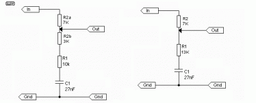
It gives you 2 versions, the version on the right is the simplest, the version on the left shows what you have, in effect, with the pot in place
In my drawing I show the pot replaced by 2 resistors, R2a - R2b. In fact they are the same as the pot, they are a voltage divider. In the drawing on the right, we just get rid of the extra resistor, R2b. Simple!
Now that you have found the setting you want with the pot (3dB you say), you can measure each leg of the pot to find out what those values are. Disconnect the ins and outs before you measure.
In my drawing below I gave R2a-R2b values of 7K & 3K. You would just subsitute the values you mesure on your pot with the adjustment the way you like it. Might be 5K-5K, or 1K-9k, whateverz.
You can see in the second drawing that I have just added R2b to R1, so R1 is now 13K. That's all you need to do. Two resistors and a cap. Pretty simple!
If any of that is not clear, just ask.
good idea to build this little circuit. Handy, isn't it?
If you want to simplify it, have a look at what I posted below.
It gives you 2 versions, the version on the right is the simplest, the version on the left shows what you have, in effect, with the pot in place
In my drawing I show the pot replaced by 2 resistors, R2a - R2b. In fact they are the same as the pot, they are a voltage divider. In the drawing on the right, we just get rid of the extra resistor, R2b. Simple!
Now that you have found the setting you want with the pot (3dB you say), you can measure each leg of the pot to find out what those values are. Disconnect the ins and outs before you measure.
In my drawing below I gave R2a-R2b values of 7K & 3K. You would just subsitute the values you mesure on your pot with the adjustment the way you like it. Might be 5K-5K, or 1K-9k, whateverz.
You can see in the second drawing that I have just added R2b to R1, so R1 is now 13K. That's all you need to do. Two resistors and a cap. Pretty simple!
If any of that is not clear, just ask.
Attachments
Hi Panomaniac,
Thanks a lot for your response! It definitely makes sense, and seems kind of simple now") Yes, this little circuit saved a lot of time and money (since I don't have a collection of filter components to try).
Yes, this little circuit saved a lot of time and money (since I don't have a collection of filter components to try).
I have one question about the impedance this circuit introduces to the pre and power amps in my system...
Using the circuit in your picture as an example, if the value R2 (or R2a) is 7k ohm, does this mean the attached preamp is driving a 7 k ohm load, and the power amp is being driven by a 7 k ohm load?
If this is the case, I guess it means technically the impedances seen by the pre / power amps are a little too low / high. I guess this is where the need for buffers arises.
Thanks again.
Andrew.
Thanks a lot for your response! It definitely makes sense, and seems kind of simple now
Yes, this little circuit saved a lot of time and money (since I don't have a collection of filter components to try). I have one question about the impedance this circuit introduces to the pre and power amps in my system...
Using the circuit in your picture as an example, if the value R2 (or R2a) is 7k ohm, does this mean the attached preamp is driving a 7 k ohm load, and the power amp is being driven by a 7 k ohm load?
If this is the case, I guess it means technically the impedances seen by the pre / power amps are a little too low / high. I guess this is where the need for buffers arises.
Thanks again.
Andrew.
arjscott said:Using the circuit in your picture as an example, if the value R2 (or R2a) is 7k ohm, does this mean the attached preamp is driving a 7 k ohm load, and the power amp is being driven by a 7 k ohm load?
No and Yes.
No, the preamp is not driving a 7K load. The load will be the input impedance of the following device in parallel with R1-C1 + 7K. So it will still be pretty high.
Yes, the source impedance is now = R2, more or less. Not a problem if the wires are sort. But certainly a problem if they are not.
sreten said:Permanent BSC can be built into the feedback loop of the power amplifier or a line stage driving a power amplifier.
A splendid idea! (got any examples to show?)
panomaniac said:
(got any examples to show?)
Hi,
Typical power amplifier will have gain 28, set by ~1K and ~ 28K.
Split the 28K into two parallel 56K resistors.
Put a capacitor in series with one of them.
6dB of baffle step. For 3dB adjust the resistor values.
/sreten.pikkujöpö said:If you want to bring up the highs,you can ad a capacitor across the R2.
Sounds interesting but I'm not quite sure what you mean by "bring up the highs"? Can you explain a bit more?
panomaniac said:
Yes, the source impedance is now = R2, more or less. Not a problem if the wires are short. But certainly a problem if they are not.
I see, thanks a lot for the clarification.
Andrew.
The cap across R2 would work as a sort of "short circuit" or shunt around the resistor for the high frequencies. Since the cap will have a lower impedance than the resistor in the high frequencies, you now have a lower R2 for the highs, but the same for the lows.
If you put a big enough cap in there, you'll get more mids and lows, too.
If you put a big enough cap in there, you'll get more mids and lows, too.
Hi Panomaniac,
Thanks. I think the next question I should be asking is where is the best place to start if I want to obtain the knowledge required to really understand filter design?
I guess one approach would be to start with the basics of electronics and keep studying until audio filter design begins to make sense.
Another approach might be to find a textbook that is aimed at people with a little electronics knowledge and the desire to understand filter design. Would the crossover section of The Loudspeaker Design Cookbook be a good place to start?
arjscott said:Would the crossover section of The Loudspeaker Design Cookbook be a good place to start?
Yes it would.
Once you understand the basics of what a cap, inductor and resistor do in a filter, you'll start to see the light. Then you can look at a schematic and say "oh yeah!" They always do the same thing, but they are used in different parts of the circuit to make the changes you want. Building blocks, really.
- Status
- This old topic is closed. If you want to reopen this topic, contact a moderator using the "Report Post" button.
- Home
- Loudspeakers
- Multi-Way
- Fixed line level BSC based on Rod Elliot's circuit