I ran a 60x60 horn model I had with an S1 of 3.2 and got a CD flare rate of 2790 hz
I did the math and I see 1" dia circle is indeed 5 sq.cm. Why then does Bill's spreadsheet start with S1 of half that?
but what about the 6.7 cm acoustic path length (for the BMS4550) inside the driver and phase plug? Will the flare rate of the phase plug determine the low end response limit?
These numbers don't sound right. S1 is the throat of the horn; an S1 of 3.2 centimeters would indicate that your throat is smaller than 1".
I have a 60x60 conical horn here in hornresp, and it has the following values:
S1 = 5.07 (1" circular throat)
S2 = 69.22 (diameter of 9.39cm, five centimeters away from the bug screen)
L12 (length of first segment) = 5cm
the flare rate at point S2 is 1,431hz.
Also, take a look at my graph, your numbers should be similar if my math is correct. (we can't assume my math is right, I'm wrong 90% of the time lol. Thank God I make software for a living and not bridges.)
Last edited:
great! On to the CD
My original S1 is 2.53 cm2. when I make S2 = 5.06 cm2 and convert to EXP, I get F12 of 4412. I hope that isn't right. If it is, I need a narrower horn or a higher crossover point and I'm beginning to understand some of the difficulties.
That's not correct unless you are using a compression driver that is smaller than 1". A 1" compression driver has a throat area of 5.067cm^2. Calculate the flare rate that it sees from what I wrote above.
nc535 said:I ran a 60x60 horn model I had with an S1 of 3.2 and got a CD flare rate of 2790 hz
I did the math and I see 1" dia circle is indeed 5 sq.cm. Why then does Bill's spreadsheet start with S1 of half that?
but what about the 6.7 cm acoustic path length (for the BMS4550) inside the driver and phase plug? Will the flare rate of the phase plug determine the low end response limit?
S1 is less than 5.067cm^2 because he is accounting for the internal structure of the compression driver. I'm not sure if he actually measured the acoustical path length, or made a physical measurement of the driver. The most accurate method is to use speaker measurement equipment and send a pulse to the speaker. The time delay (or time of flight) can be used to calculate the real acoustical center of the driver. This is different than the physical measurement of the diver's pathway. The acoustic center is usually more forward than what the driver physically measures.
The 6.7cm distance for the BMS4550 comes from an actual acoustical measurement. The internal flare is of no concern. You want to know what your horn is doing. Start with 5.07cm^2 and perform the flare rate calculation based on the distance it takes to expand to 10.14cm^2.
Last edited:
OK!The graph above shows the local flare rate of various horn geometries, and Paralines too.
Based on John's instructions here: http://www.diyaudio.com/forums/mult...e-bandpass-mid-unity-horn-81.html#post3468056
I believe that I would go through the following process if I was designing a 50x50 Synergy horn:
1) The first step in figuring out the location of the tap is to insure that the tap's location is *beyond* the transition from the high frequency horn, to the midrange horn. (IE, we're making a 'horn on a horn', and the two horns need to 'get out of each others way') If I opt to use an xover point of 1000hz and a 50x50 horn, then the end of the high frequency horn is 6.75cm from the throat.
2) Now that I know where my high frequency horn ends, I need to see the impact of the quarter wave reflection. Looking at the same graph, I see that the quarter wave reflection will happen at 1440hz. That's actually a little bit too high, since I want to use an xover point of 1000hz. We're going to get an overlap between 1440hz and 1000hz. To get things to line up better, I push the midrange taps out to 8.75cm. That moves the quarter wave dip down by 500hz, and it also gets the midrange further 'out of the way' of the compression driver. (Remember, the compression driver basically 'can't see' the midranges if you do this right.)
Naturally, you'll notice that these two numbers are a fraction of an inch apart.
You keep writing quarter wave length. The cancellation notch is a half wave length distance - i.e. 180 degrees out of phase = 1/2 WL.
This is not the case. In every case I've found the tap in point to be the reason why the mids drop off too early. Even piece of crap Curtis Mathes mids can work well into the 2KHz to 3KHz range.
Thanks again for all the info! I've been saving a lot of this stuff from you, Danley, and others in a word doc so I'm not always hunting around the net if there's something I forgot/not making sense.
I made my comment assuming PB knows that stuff anyways and had optimized that design to work correctly.
One thing I've been thinking about lately is where the mids tap into the horn. I understand the reasoning behind the placement where the compression driver won't "see" the mid ports, and I also have an idea of why a square horn is better to "hide" the ports than a round horn. I've seen the measurements people have made with and without the ports showing basically no effect. I wonder about this. It would be nice to see that sort of test with a full set of polars out to 90° with/without the ports. I wonder about the effect of the ports when I look at Geddes' waveguides. The Summa uses a 15" 'guide for pattern control down to 900hz. In that design I assume the waveguide "sees" the compression driver output along its entire length out to the mouth. I may be wrong about that.
Would this not be the case with a conical Synergy horn as well? Where the horn controls the directivity of the comp driver past the point where it's being loaded (probably using that term wrong) and past the area where the mids tap in, causing interference with the comp driver output off axis?
I'm sure I don't have enough knowledge about horns/waveguides to grasp this, and my intention isn't to knock the Synergy horn (I plan on building one) but to get a better understanding of what is going on.
You keep writing quarter wave length. The cancellation notch is a half wave length distance - i.e. 180 degrees out of phase = 1/2 WL.
As I understand it, the cancellation occurs when the sound is 180 degrees out of phase. (one half wavelength.)
But the 'rule of thumb' for the notch is one quarter wavelength, because the sound travels UP the horn to the throat, reflects, and then travels back down.
So, one quarter UP the horn is one quarter wavelength, one quarter DOWN the horn from the throat to the midrange taps is one quarter wavelength, for a total distance traveled of one half wavelength... But the distance we're looking for is one quarter wavelength long.
Thanks again for all the info! I've been saving a lot of this stuff from you, Danley, and others in a word doc so I'm not always hunting around the net if there's something I forgot/not making sense.
I made my comment assuming PB knows that stuff anyways and had optimized that design to work correctly.
One thing I've been thinking about lately is where the mids tap into the horn. I understand the reasoning behind the placement where the compression driver won't "see" the mid ports, and I also have an idea of why a square horn is better to "hide" the ports than a round horn. I've seen the measurements people have made with and without the ports showing basically no effect. I wonder about this. It would be nice to see that sort of test with a full set of polars out to 90° with/without the ports. I wonder about the effect of the ports when I look at Geddes' waveguides. The Summa uses a 15" 'guide for pattern control down to 900hz. In that design I assume the waveguide "sees" the compression driver output along its entire length out to the mouth. I may be wrong about that.
Would this not be the case with a conical Synergy horn as well? Where the horn controls the directivity of the comp driver past the point where it's being loaded (probably using that term wrong) and past the area where the mids tap in, causing interference with the comp driver output off axis?
I'm sure I don't have enough knowledge about horns/waveguides to grasp this, and my intention isn't to knock the Synergy horn (I plan on building one) but to get a better understanding of what is going on.
I don’t fully understand your questions, but will take a stab at what I think you are asking. I understand not being able to articulate what you want to know. This happens to all of us. Don’t sweat it.
Let’s use an example where we are crossing over a compression driver at 1200Hz. At this frequency the full wave length is about 28.56cm long. If we take this compression driver and load it into a conical horn, the horn will stop providing a load to the driver around where it expands to 64.91cm^2. Once you expand to beyond an area that is greater than one full wave length, the driver can no longer exert any pressure against the horn walls. (The juvenile analogy I use is it becomes like throwing a hotdog down a hallway.) Now take this a step further and use a square/rectangular horn instead of an axis symmetrical horn. The pressure in the corners drops even sooner than the flat side walls. Tuck your entry ports in the corners, and there is almost zero chance of them interfering with the compression driver’s output. To fully ensure you won’t get interference, you want to tap the mids in where the area is slightly larger than 64.91cm^2. We design to have a small gap between when the compression driver unloads, and when the mids turn on. There will be enough summing at the crossover point to provide a flat power response. There should not be a dip in response.
OK!
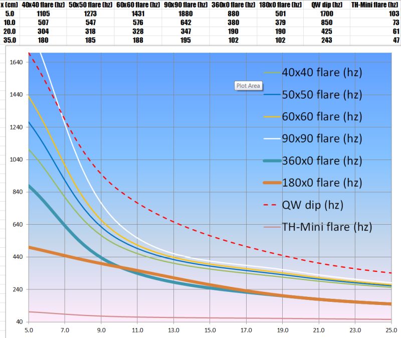
The graph above shows the local flare rate of various horn geometries, and Paralines too.
Based on John's instructions here: http://www.diyaudio.com/forums/mult...e-bandpass-mid-unity-horn-81.html#post3468056
I believe that I would go through the following process if I was designing a 50x50 Synergy horn:
1) The first step in figuring out the location of the tap is to insure that the tap's location is *beyond* the transition from the high frequency horn, to the midrange horn. (IE, we're making a 'horn on a horn', and the two horns need to 'get out of each others way') If I opt to use an xover point of 1000hz and a 50x50 horn, then the end of the high frequency horn is 6.75cm from the throat.
2) Now that I know where my high frequency horn ends, I need to see the impact of the quarter wave reflection. Looking at the same graph, I see that the quarter wave reflection will happen at 1440hz. That's actually a little bit too high, since I want to use an xover point of 1000hz. We're going to get an overlap between 1440hz and 1000hz. To get things to line up better, I push the midrange taps out to 8.75cm. That moves the quarter wave dip down by 500hz, and it also gets the midrange further 'out of the way' of the compression driver. (Remember, the compression driver basically 'can't see' the midranges if you do this right.)
Naturally, you'll notice that these two numbers are a fraction of an inch apart.
The graph above uses a 'rule of thumb' for the cancellation notch. And that rule of thumb is based on maths that I describe in post #829.
Unfortunately, there's a problem with this approach, which is that it's a rule of thumb that doesn't include a pile of factors. These factors include, but are not limited to:
1) The size of the coupling chamber will change the frequency of the notch. For instance, if the coupling chamber is 2.5cm deep, that'll have an impact
2) The apparent location of the compression driver *and* the midranges is dependent on frequency
3) The amount of midrange energy radiated into the throat will decrease as wall angle increases. (IE, a 20x20 horn is going to radiate more energy into the throat than a 135x135 horn.)
Lots and lots of variables right?
So in this instance, our best option is to bust out Hornresp and Akabak and simulate real horns with real midranges.

Which is just what I did to produce the graph above.
This graph intends to simulate the exact thing that John asked for; it shows the relation of the quarter wave notch to the flare rate. But instead of using a 'rule of thumb' to calculate the notch, I simmed an actual horn, with four of the Misco JCRTF5-B mids. And I didn't use a 'rule of thumb' for the notch; I found the notch on the frequency response prediction, and popped it into Excel.
The solid red line is the local flare rate of a 40x40 conical horn;
the dashed red line is the frequency that the notch happens;
the solid white line is the local flare rate of a 60x60 conical horn;
the dashed white line is the frequency that the notch happens.
Both the 40x40 horn use a 1" circular throat, and a square mouth.
I noticed something that's a bit interesting about the graph. As John has noted, we don't want the midrange taps too close to the throat. But the 40x40 horn makes this a lot easier. For instance, if you want to cross the compression driver over at 1000hz, you need a 40x40 horn that's 6.5cm deep. But with the 60x60 horn, you need one that's 10cm deep. And that extra 3.5cm doesn't SEEM like a big deal, but it really is. If we put those midrange taps at 6.5cm in the 40x40 horn, we get a notch at 2000hz. Due to the notch being so high, we have the luxury of moving the midrange taps a bit forward, away from the compression driver. For instance, let's say you were building a 40x40 horn, and you opted to move the midrange taps a full inch forward of where the high frequency horn passes the baton to the midrange horn. In this scenario, your taps will be at the nine centimeter mark, where you'll get a notch at 1500hz. Your mids will be further 'out of the way' of the high frequency horn.
But compare that math with the 60x60 horn:
With the 60x60 horn and a 1khz crossover for the compression driver, we need a horn that's 10 centimeters deep. But placing the midrange taps at the ten centimeter mark puts a dip in our midrange output at just 750hz! So now we have the OPPOSITE problem of the 40x40 horn. Instead of having the luxury of moving the midrange taps forward, we have a catch-22. If we move the midrange taps forward to get them 'out of the way' of the compression driver, we'll have a notch in the output that will be basically very very difficult to fix. If the midrange taps are too far forward in the 60x60 horn, the horn geometry may be basically unusable. Now if we move those midrange taps back towards the throat, we're going to move the dip up in frequency, and that's going to improve the frequency response of our midranges. But at the same time, our midrange taps are beginning to stomp on the high frequency horn. Now, obviously, there's a bunch of things you can do to make the response look better. Small midrange holes and frustums go a long way. But the best solution - by far - is to simply get the midrange segment of the horn 'out of the way' of the high frequency horn.
Interesting huh?
")
I believe that this graph shows that there are many combinations of crossover point and wall angle that simply won't work with the average 1" compression driver.
Narrow the wall angles, and things get easier, but it also makes for a very big horn. I might argue that even a 60x60 horn is pushing it, unless you use a coax at the throat.
50x50 seems like a nice 'sweet spot', with a good balance of locations for the midrange taps, while not requiring a horn that's as hu-mon-gous as the 40x40 horns.
If anyone wants to create their own graphs of the data, let me know, I think these tables give everyone some 'guidelines' of what combinations work, without having to fish around in the dark using random combinations of driver and horn.
Last edited:
As I understand it, the cancellation occurs when the sound is 180 degrees out of phase. (one half wavelength.)
But the 'rule of thumb' for the notch is one quarter wavelength, because the sound travels UP the horn to the throat, reflects, and then travels back down.
So, one quarter UP the horn is one quarter wavelength, one quarter DOWN the horn from the throat to the midrange taps is one quarter wavelength, for a total distance traveled of one half wavelength... But the distance we're looking for is one quarter wavelength long.
I don't know anything about this "rule of thumb" you are talking about. If you stay within a 1/4 WL then cancellation is not likely, as with the Paraline designs. However, the Unity/Synergy is specifically designed so we WILL get a cancellation notch. You have to look at it like this, the whole wave length travels down the throat and comes back to the port entry. This is a bisection of the whole wave length, thus 180 degrees is half a wave length. Go ahead and fire up Horn Response or Akabak if you don't believe me.
An externally hosted image should be here but it was not working when we last tested it.

You know what I need to do? I need to run these numbers on some widely available waveguides.
For instance, if I ran these measurements on my 18Sound XT1086 and my QSC waveguides, I could figure out with fairly high certainty where the optimum tap location should go.
And one thing that I've noticed with Unity horns is that everything just 'snaps' into place when you get all the geometry correct. And conversely, when the geometry is wrong it's hard/impossible to get it to work.
Taken to the extreme, John had some Paralines that he was running with no xover at all, IIRC. That's pretty amazing when you think about it; the crossover on the loudspeakers is basically acoustical, not electrical.
I could do the maths by simply making a mold out of both horns, then slicing the mold into layers, and measuring each layer.
And that would save *everyone* the trouble of building horns and guessing or calculating where the taps should go. Because it's not like the location of the taps is open to debate; it's basically dictated by the xover point, the area of the horn, and the flare rate. So if I made a table for widely available horns, all we'd need to do is select a xover point, select a waveguide, look up the location on my table, and drill the taps.
Last edited:
I don't know anything about this "rule of thumb" you are talking about. If you stay within a 1/4 WL then cancellation is not likely, as with the Paraline designs. However, the Unity/Synergy is specifically designed so we WILL get a cancellation notch. You have to look at it like this, the whole wave length travels down the throat and comes back to the port entry. This is a bisection of the whole wave length, thus 180 degrees is half a wave length. Go ahead and fire up Horn Response or Akabak if you don't believe me.
I call it a 'rule of thumb', because Akabak and Hornresp shows us that the actual notch occurs at neither 1/4WL or 1/2WL; it's somewhere in between and it depends on at least half a dozen factors. The big one is wall angle and the acoustic source of the midranges, since the actual location of the mids and the acoustic source of the midranges is frequency dependent.
Audio Asylum Thread Printer
From Tom Danley:
Hi
Keep in mind that a horn is in effect a “high pass filter”, that filter frequency is set partly by how fast the area expands. While an exponential horn has a constant “high pass” frequency, a conical horn has a variable expansion rate. At the apex the expansion is rapid, like a HF horn. As you move from the apex, the expansion rate slows down.
The idea here is to tap into the horn body at points where the expansion rate is appropriate for the drivers connected to it at each point.
The holes minimize the discontinuity in the horn path and the combination of the air under the cone and acoustic mass in each hole forms an acoustic low pass filter positioned just above where the electrical crossover is.
While the expansion rate sets the low cutoff for each section, the upper F is set by the acoustic filter and the 1 / 4 wl acoustic distance to the throat from any driver set. At that point there is a cancellation notch and the onset of the acoustic low pass filter (both of which reduce what ever distortion the driver produces).
Have fun
Tom
The shortest route is to pick your horizontal dispersion angle and length, then set the vertical dispersion angle to whatever it needs to be to make all the math correct. This normally results in a less than desirable vertical dispersion angle, but it was very handy when running simulations and gaining an understanding of the variables at play. This stuff is maddening. I find I have to step away from it frequently otherwise it gets the best of me. If I had an extra $6000 laying around I would have already bought a pair of SH-46 and been done with it.
I call it a 'rule of thumb', because Akabak and Hornresp shows us that the actual notch occurs at neither 1/4WL or 1/2WL; it's somewhere in between and it depends on at least half a dozen factors.
You got that right. It doesn't show it exactly where the math says, but when you examine the phase, it is right on the dot.
The big one is wall angle and the acoustic source of the midranges, since the actual location of the mids and the acoustic source of the midranges is frequency dependent.
Audio Asylum Thread Printer
From Tom Danley:
Hi
Keep in mind that a horn is in effect a “high pass filter”, that filter frequency is set partly by how fast the area expands. While an exponential horn has a constant “high pass” frequency, a conical horn has a variable expansion rate. At the apex the expansion is rapid, like a HF horn. As you move from the apex, the expansion rate slows down.
The idea here is to tap into the horn body at points where the expansion rate is appropriate for the drivers connected to it at each point.
The holes minimize the discontinuity in the horn path and the combination of the air under the cone and acoustic mass in each hole forms an acoustic low pass filter positioned just above where the electrical crossover is.
While the expansion rate sets the low cutoff for each section, the upper F is set by the acoustic filter and the 1 / 4 wl acoustic distance to the throat from any driver set. At that point there is a cancellation notch and the onset of the acoustic low pass filter (both of which reduce what ever distortion the driver produces).
Have fun
Tom
Don't you just love how the patent and what the device actually is differes so much?
The shortest route is to pick your horizontal dispersion angle and length, then set the vertical dispersion angle to whatever it needs to be to make all the math correct. This normally results in a less than desirable vertical dispersion angle, but it was very handy when running simulations and gaining an understanding of the variables at play. This stuff is maddening. I find I have to step away from it frequently otherwise it gets the best of me. If I had an extra $6000 laying around I would have already bought a pair of SH-46 and been done with it.
True! It's not a coincidence that I like building bicycles and I like building Unity horns. Both are devices where changing ONE variable changes EVERYTHING. I think it's kind of interesting, because few things work like this. For instance, I can build a two-way loudspeaker, and if I use a midrange or a tweeter that's a little bit "off" I can still fix it.
But not with a Unity; everything counts.
And bikes are the same way. It's the reason that nearly every road bike in the world looks like every other road bike. After years and years and years of refinement they've all converged on a similar geometry, because there's a narrow band of geometries which work.
All the horns that I’ve listened (a couple of them were my own designs) to that go through a geometry flip just sound a bit weird. Something just sounds off about them. I really can’t explain any better. I agree the TPL-150 is an excellent driver. It just doesn’t lend itself to being implemented in a Unity/Synergy design.
You can implement any compression driver you like. I don’t know much about the CD10ND, but have listened to the CP380/M and CP385Nd in several designs. Both were very good sounding in their designs. I would think they would perform fine in a Unity/Synergy design, but I can’t be certain.
Correct, moving the entry holes down the horn will increase the cross sectional area they tap into too much and you will not be able to reach 1KHz. At the same time the further you move down the horn, the lower the local area flare goes. You have to balance the ½ wave cancellation notch distance with the area of the horn where you tap in. It just so happens this is much easier to do with a compression driver.
The ideal balance is when the circumference of the area the mids tap into is equal to one wave length of the highest frequency, and the distance between the acoustical center of compression driver and mids is half a wave length of the highest frequency. In your case of 1.5KHz this would mean that you want to tap the mids into the horn with an area of 41.53cm^2 that is 11.42cm from the acoustical center of the compression driver.
Thanks again, John!
/Thomas
I don’t fully understand your questions, but will take a stab at what I think you are asking. I understand not being able to articulate what you want to know. This happens to all of us. Don’t sweat it.
I'll try to explain what I was getting at with the Summa reference. I understand the reasoning that the comp driver won't exert any pressure on the horn walls once its output is past the point in the horn where the circumference is greater than the wavelength of the lowest freq we want to achieve (1200hz in your example). This makes sense since as you've been hammering home the conical horn has a variable flare rate.
Where my confusion lies is with e.g. the Summa's 15" waveguide. From pictures I'd say that 15" includes the radius transition to the baffle. Taking a guess, the radius begins where the waveguide is about 10-12" in diameter. For the Summa to hit 900hz, we're looking at a circumference of about 15", which is a diameter of 4.8". Obviously Earl's waveguides are much bigger than this (4.8" dia), to control the directivity to match a woofer at the xo. It stands to reason in my mind then that the compression driver in the Summa is exerting some pressure on the waveguide walls past the 15" circumference, otherwise it wouldn't need to be as large as it is. I also understand that the radius to the baffle helps control directivity at the low end to prevent waist-banding the polar pattern there, contributing to the larger size.
Drawing that line of reasoning to the Synergy horn, it seems to me that the horn will be constraining the comp driver's directivity past the area where the flare rate no longer loads the device (a catch-22 to your line of reasoning, I know). This would be the region where we are tapping the mids in, and I wonder if at off axis angles approaching the horn wall angle (for a 60x60 then we would say 30°) if the comp driver would in fact "see" the mid ports? Or does the fact that we are using square horns here mitigate that effect like you say? Or is comparing one of Earl's waveguides to a conical horn comparing apples to oranges?
If that isn't clear as mud I'll make some drawings
The pressure in the corners of a square/rectangular horn is substantially lower than an axis symmetrical horn. This greatly diminishes the effect you are describing. Each type of horn has its positives and negatives. Its up to the designer to determine how they want to solve their problems. Both the Summa and the Synergy horns are great products.
Back to the CD lower cutoff frequency for a moment
I had to step away from the conversation on the weekend but caught up last night. I ran the 5 to 10 sq. cm. flare rate numbers for a range of horn angles, getting roughly 4 Khz for a 90 degree horn and 2 khz for a 60 degree horn. I found TS parameters for the BMS4550 in an akabak script posted by JLH (thanks) and simulated it on those horns. I did some research and found Bill Waslo's 90x60 Cosyne crossing right around 4 khz. OTOH, several 40 and 60 degree horn threads showed crossovers at/around 1 khz, half the calcuated cutoff.
As you can see in the attached chart and no doubt expected, the cutoff is quite gradual in a conical horn. Its apparent both why Bill pushed his crossover as high as possible and why in a narrower horn you can get away with crossing over under the calculated cutoff frequency. The sim was run at just over 100W into the CD. The driver is at 1 mm excursion at 800 hz or so on the 60 degree horn and 1 khz on the 90 degree horn trace.
I'm now torn between going with the 256x90 horn that fits my intended corner placement better and with a 60x60 which would be an easier design and not suffer from pattern flip.
Thanks to JLH and PB and all for the enlightenment of the last few days.
That's not correct unless you are using a compression driver that is smaller than 1". A 1" compression driver has a throat area of 5.067cm^2. Calculate the flare rate that it sees from what I wrote above.
S1 is less than 5.067cm^2 because he is accounting for the internal structure of the compression driver. I'm not sure if he actually measured the acoustical path length, or made a physical measurement of the driver. The most accurate method is to use speaker measurement equipment and send a pulse to the speaker. The time delay (or time of flight) can be used to calculate the real acoustical center of the driver. This is different than the physical measurement of the diver's pathway. The acoustic center is usually more forward than what the driver physically measures.
The 6.7cm distance for the BMS4550 comes from an actual acoustical measurement. The internal flare is of no concern. You want to know what your horn is doing. Start with 5.07cm^2 and perform the flare rate calculation based on the distance it takes to expand to 10.14cm^2.
I had to step away from the conversation on the weekend but caught up last night. I ran the 5 to 10 sq. cm. flare rate numbers for a range of horn angles, getting roughly 4 Khz for a 90 degree horn and 2 khz for a 60 degree horn. I found TS parameters for the BMS4550 in an akabak script posted by JLH (thanks) and simulated it on those horns. I did some research and found Bill Waslo's 90x60 Cosyne crossing right around 4 khz. OTOH, several 40 and 60 degree horn threads showed crossovers at/around 1 khz, half the calcuated cutoff.
As you can see in the attached chart and no doubt expected, the cutoff is quite gradual in a conical horn. Its apparent both why Bill pushed his crossover as high as possible and why in a narrower horn you can get away with crossing over under the calculated cutoff frequency. The sim was run at just over 100W into the CD. The driver is at 1 mm excursion at 800 hz or so on the 60 degree horn and 1 khz on the 90 degree horn trace.
I'm now torn between going with the 256x90 horn that fits my intended corner placement better and with a 60x60 which would be an easier design and not suffer from pattern flip.
Thanks to JLH and PB and all for the enlightenment of the last few days.
Attachments
256x90 hornAs you can see in the attached chart and no doubt expected, the cutoff is quite gradual in a conical horn. Its apparent both why Bill pushed his crossover as high as possible and why in a narrower horn you can get away with crossing over under the calculated cutoff frequency. The sim was run at just over 100W into the CD. The driver is at 1 mm excursion at 800 hz or so on the 60 degree horn and 1 khz on the 90 degree horn trace.
I'm now torn between going with the 256x90 horn that fits my intended corner placement better and with a 60x60 which would be an easier design and not suffer from pattern flip.
?1mm excursion would sound totally gross, the 4550 has around 8% distortion at 111.7 dB (one meter equivalent) with a dual sine wave tone of 1046 &1865 Hz in to a 13 x13 degree conical horn.
The 13 x13 degree Maltese horn has a much lower cutoff frequency and much higher on axis sensitivity (around 115 dB one watt one meter) than your sims.
My measurements suggest Xmax probably on the order of .2 mm or less for the BMS 4550. Nice sounding driver, but it won't sound nice at 100 watts at 800 Hz on a 60 x 60 conical horn!
If you want to actually hear how the driver sounds at high drive levels on a conical horn, check out this thread:
http://www.diyaudio.com/forums/multi-way/212240-high-frequency-compression-driver-evaluation.html
A shorter version (only 3000 rather than 8000 words, and a lot less pictures) can be found here:
High Frequency Compression Driver Evaluation
The sound files in the soundforums.net posts do not have the low frequency portion of the music mixed in, listening to the HF horn alone makes it easier to hear the difference in sound quality and distortion between the various drivers all tested under the same conditions.
Art
Thanks, Art.
256x90 = typo, horn model was 90x60 big enough to keep pattern control down to 256 hz
I wouldn't dream of listening at that excursion either. It was just wherer I happened to do the simulation. I think I'll be down in the 1-10W region, certainly RMS wise, don't know about the occasional peak. And I'll push the xover up to 1.5 or 2 khz, if I can.
90 x 60 pattern control down to 256 Hz will require a horn with a mouth around 4.4 feet (1.6 meters) wide in the 60 degree dimension, that's rather large.Thanks, Art.
256x90 = typo, horn model was 90x60 big enough to keep pattern control down to 256 hz
- Home
- Loudspeakers
- Multi-Way
- Suitable midrange cone, for bandpass mid in Unity horn.