I'm now working on S3, which I'm thinking of making 80 x 60. I don't actually need 90 degrees dispersion. A few things happen as you change the coverage pattern. One is that narrowing it makes it harder to mount drivers. Another is that you tend to lose a bit of bottom end extension. Also you tend to make the mouth smaller, resulting in a loss of pattern control at a higher frequency. In S2, horizontally I had a constant beamwidth down to 280 Hz where there was a big mouth and 90 degrees. Vertically, where I had 40 degrees, pattern control is lost much sooner. The result is pattern flip. The narrow coverage only occurs up higher, and in the midrange the pattern starts to get more broad again.
Looking around for some cheap midranges to play with, I ran into these:
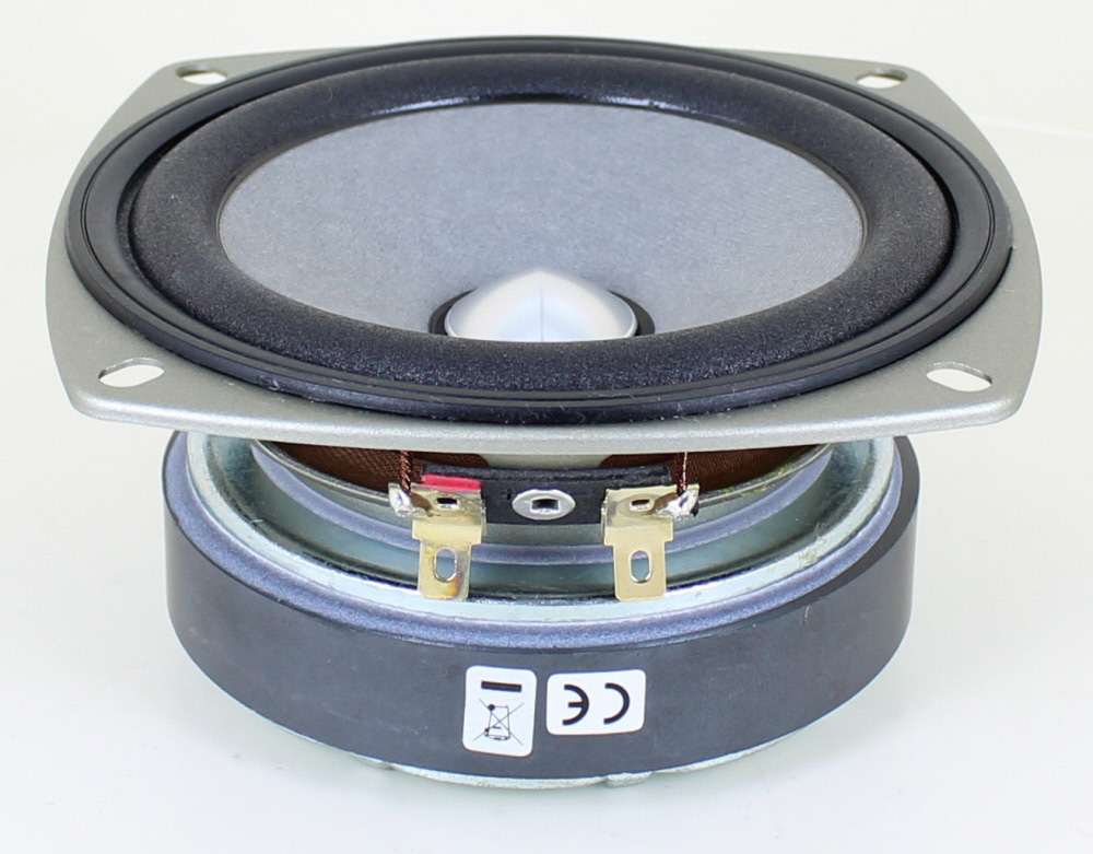
2" Paper Cone Midrange Tweeter 4 Ohm 289-127
They are open back, but the resonance is high and the compliance is stiff. Even with a big back chamber they seem to work pretty well with HornResponse (the volume behind does not affect it much). Not the most efficient in the world, but with 2" diameter, it can be pushed nice and high in frequency. Assuming the given parameters are close, of course. The price is very cheap for experimenting, looking at 4 or 6 in a synergy horn with a high upper crossover to a small compression driver.
I don't know how many they have, will have to stop up and ask.
My sims are suggesting good top end extension is possible with the Celestion 4". Here's an example modelled in both Hornresp and Akabak:
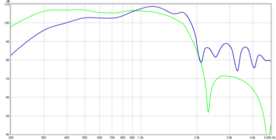
Green is Hornresp
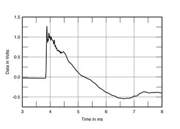
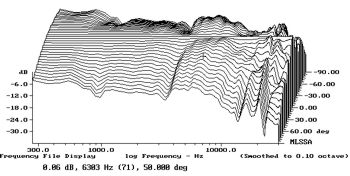
Which one is more accurate? Well here's both against a measured example where I put the Celestion 4" on S1, just a single sample driver and then I modelled it:
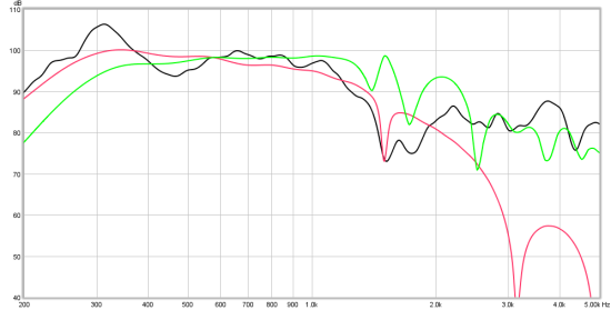
Here Hornresp is red
I have found that one can get more out of band output than expected from Hornresp - Akabak is better at predicting that. However, down to the first peak, I've had better results with Hornresp, also with the bottom end extension. Perhaps that changes when one learns to drive Akabak properly, as I've just exported the script from Hornresp. Yes - cheating!
Green is Hornresp
Which one is more accurate? Well here's both against a measured example where I put the Celestion 4" on S1, just a single sample driver and then I modelled it:
Here Hornresp is red
I have found that one can get more out of band output than expected from Hornresp - Akabak is better at predicting that. However, down to the first peak, I've had better results with Hornresp, also with the bottom end extension. Perhaps that changes when one learns to drive Akabak properly, as I've just exported the script from Hornresp. Yes - cheating!
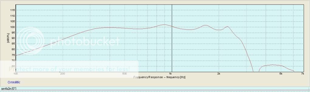
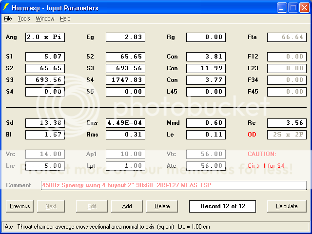
Here is a HornResponse sim using 4 of these 2" midranges on a 90x60 conical 450Hz unity type waveguide. I've also seen these drivers at Marlin P Jones, not bad for a buck and a half each.
Looking around for some cheap midranges to play with, I ran into these:
2" Paper Cone Midrange Tweeter 4 Ohm 289-127
They are open back, but the resonance is high and the compliance is stiff. Even with a big back chamber they seem to work pretty well with HornResponse (the volume behind does not affect it much). Not the most efficient in the world, but with 2" diameter, it can be pushed nice and high in frequency. Assuming the given parameters are close, of course. The price is very cheap for experimenting, looking at 4 or 6 in a synergy horn with a high upper crossover to a small compression driver.
I don't know how many they have, will have to stop up and ask.
Last edited:
Got some of the little mids...
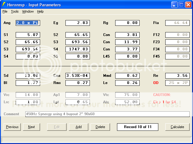
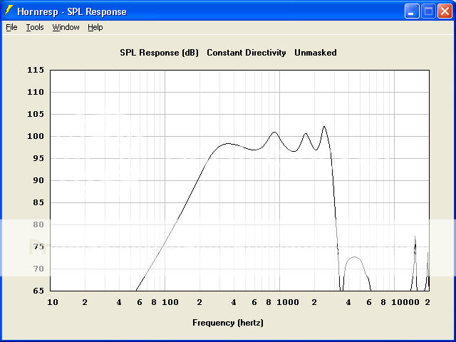
Went up to Parts Express today and picked up 9 of these little guys. I measured the T/S parameters, a little off from what they were quoted, but no less usable. Here are shots of the T/S, new HornResp values, and simulated response curve for a 4x4 arrangement:
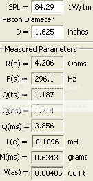
They have on the order of 300 of these in stock.
These won't be easy to seal the backs on because the terminals are so close to the outer edge, but a lot of volume on the back doesn't have much if any effect (just stuff the back volume with damping). Could just put the whole synergy horn in a box for the back waves from these drivers.
I'm also getting some of the Celestion 4" mids that Paul Spenser recommends. These 2" ones though might be a good match for use with a CD that cuts in at about 2kHz, I'm hoping.
Went up to Parts Express today and picked up 9 of these little guys. I measured the T/S parameters, a little off from what they were quoted, but no less usable. Here are shots of the T/S, new HornResp values, and simulated response curve for a 4x4 arrangement:
They have on the order of 300 of these in stock.
These won't be easy to seal the backs on because the terminals are so close to the outer edge, but a lot of volume on the back doesn't have much if any effect (just stuff the back volume with damping). Could just put the whole synergy horn in a box for the back waves from these drivers.
I'm also getting some of the Celestion 4" mids that Paul Spenser recommends. These 2" ones though might be a good match for use with a CD that cuts in at about 2kHz, I'm hoping.
I bought a box of those for some line arrays...this looks more interesting. Nice little driver. Also have a pair of de250's. I think I have a change of plans now.
Actually these horns *are* an array. In a lot of ways, they're similar to WMTMW array, but folded around a horn.
It is possible, though most ribbons require a crossover point higher than the bandpass mids would reach, requiring the ribbon, 2" cone mids, 6" cone mids, and woofers. Getting the crossover to work would be more tricky than using a compression driver.Hi guys.
Is it possible to use ribbon instead of compression driver in Unity horn?
The ribbon HF vertical dispersion would be more narrow than the rest of the drivers, so the horn would no longer be constant directivity, one of the nice features of a Unity style horn.
Would it be possible to do a Unity horn with one driver instead of five?
Here's the idea I had. Someone tell me this is a stupid idea, or else I'm going to place an order with Madisound this morning
")
An externally hosted image should be here but it was not working when we last tested it.
An externally hosted image should be here but it was not working when we last tested it.
In the Danley SM-60M and SM-60F, there is a 5" coaxial at the throat of the horn. The throat of the horn is connected to the compression driver in the throat of the 5" midrange, and the woofer cone is 'tapped' into the horn a bit further down the horn's axis.
What if you took one of these $48 Fostex woofers, and used it in lieu of the BMS Coax?
An externally hosted image should be here but it was not working when we last tested it.
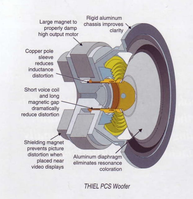
I got the idea from Thiel's "coaxial", which is basically a 3" aluminum midrange where the dustcap is decoupled from the woofer cone.
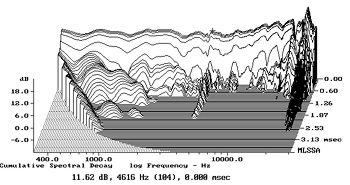
The step response, directivity, and waterfall plot are as good as I've seen from any two-way. The frequency response is 'hot' in the very top octave, but this is actually a bonus for horn loading, because it gives us some extra efficiency in an octave where the horn is too large to do it for us. (IE, with a 1" throat we're only getting gain to 13500hz due to the geometry of the throat.)
If I did this, the horn itself would look basically identical to the SM-60F or the SM-60M. The main difference is that the throat of the horn is mated to the dustcap of the Fostex woofer, instead of being mated to a compression driver. This would require some tight tolerances, but I'm pretty handy with fiberglass fabrication. The gap between the dustcap and the horn throat would have to be less than an eighth of an inch.
The idea is that the dustcap on the Thiel and the Fostex is behaving like a tweeter at high frequencies. The efficiency of this will be nowhere near the BMS, but once horn loaded, I wouldn't be surprised if the efficiency is in the mid 90s.
Best of all, it eliminates the expense and complexity of the compression driver and it's crossover. On my first Unity project, I spent over $500 and two weeks of time on that component of the design. So this would be a significant cost savings if it worked.
I imagine the most challenging part would be tweaking the size of the midrange ports; you would basically adjust them until you achieved a smooth transition from the radiation of the dustcap at the throat to the radiation of the midranges at the taps.
We wouldn't have the luxury of shaping the high frequency response electrically; basically the crossover is mechanical.
One obvious concern is that radiation from the midranges would 'leak' through the throat of the waveguide. I think this can be reduced a couple of ways. The first is by using a REALLY small gap between the throat and the dust cap. For instance, if you can keep the gap between the dustcap and the throat down to a tenth of an inch, then the midrange holes will be about 10x larger than that gap.
Basically, the air under the midrange cones should take "the path of least resistance."
The second thing that reduces inteference between the edge of the cone and the 'tweeter' in the center is that the center is beaming above 14khz. Basically, due to it's size, it doesn't "see" the horn walls above 14khz.
All of this is is conjecture of course
But considering I could build one for sixty bucks, it's a heck of a lot more tempting than tackling the $500 or so needed for a 'real' one.
One tantalizing idea about all of this is that if it worked, you might be able to do a Unity horn with no electrical crossover(!) Basically the size of the midrange ports and the volume of the coupling chamber would be used to tune the response.
How would you get a seal between dustcap and horn throat?
The Danley horn (as I understand it) gets around that problem by basically sticking the horn mouth down the pole-piece.
But with a dustcap that's only decoupled at high frequencies, it'll still move a few mm at lower frequencies.
An old Tannoy ICT driver might be another alternative, because I think it could be used like a coax.
I already have a pile of midranges and waveguides and horns at home; I think that I will try to build one of these tonight.
If anyone wants to give it a go, here are the parts that I am going to use.
#1 - QSC PL-000446GP, $35 from Parts Express
While the QSC isn't the same dimensions as the Danley SM-60M, it's as close as I got laying around. The QSC is 60x90 degrees; the Danley is 60x60.
#2 - Faital Pro 3FE20, $46 from Loudspeakers Plus.
Faital Pro 3FE20 3" Speakers - Faital Pro 3FE20 mid-high speaker has a wide frequency range from 100Hz to 20kHz and has a lightweight neodymium magnet - Faital Pro 3FE20 40 watt 3" has an efficiency of 91dB SPL for all high quality mid-high applicati
I think the Fostex 5" from Madisound will work better, and it's cheaper, but I have some Faitals laying around. I considered the $10 Pyle from PE, but I think you want a woofer where the dustcap is the same size as the voice coil. This is important for high frequency response because we basically want the dustcap to be rigidly connected to the voice coil at high frequencies, while the cone itself is 'decoupled' so that the high frequency radiation is coming from the dustcap, NOT the cone and the surround. Taken to the extreme, i would use a razor to cut the cone away from the voicecoil, then re-connect it with a rubber ring in the gap betwen the cone and the dustcap. The rubber ring will decouple the cone at high frequency by absorbing the high frequency vibrations which would normally be radiated by the cone. At low frequency (below 2khz) the cone excursion exceeds the ring's ability to absorb it, and the cone "re-couples" with the dust cap.
I hope
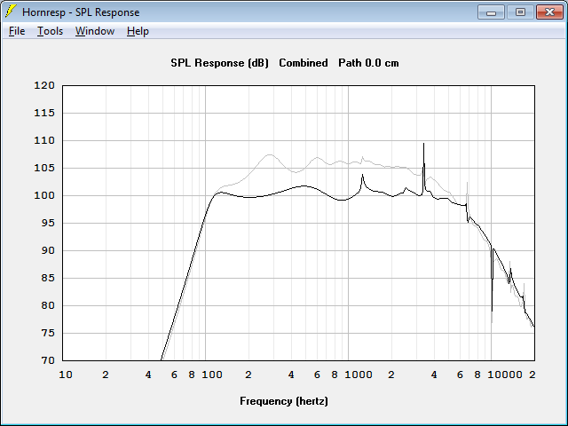
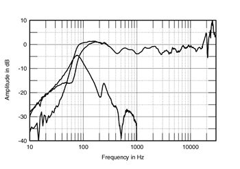
This is the predicted frequency response of the Faital 3FE20 on a couple of horns.
The grey graph is a response graph for a 60x60 horn with a 16" x 16" mouth, basically similar to the Lambda Unity
The black line is the QSC waveguide, with a 14" x 10" mouth, and a much wider directivity.
The Faital is vented. The efficiency is very low - just 90dB. I have to keep excursion as low as possible, so maximum SPL may be as low as 100dB. The maximum SPL depends a lot on the gap betwen the throat of the waveguide and the dust cap ("tweeter") of the Faital.
The 60x60 horn has much higher midrange efficiency, but the 90x40 horn has a predicted rolloff at 7700hz. So hopefully if the dustcap 'decouples' it will radiate right down the waveguide, as if it wasn't even there.
So basically you'd get horn gain down to around 500hz, directivity control from 1khz to 14khz, and then at 14khz the high frequencies basically don't "see" the waveguide and the dustcap is radiating as if it was on a flat baffle.
If anyone wants to give it a go, here are the parts that I am going to use.
#1 - QSC PL-000446GP, $35 from Parts Express
An externally hosted image should be here but it was not working when we last tested it.
An externally hosted image should be here but it was not working when we last tested it.
While the QSC isn't the same dimensions as the Danley SM-60M, it's as close as I got laying around. The QSC is 60x90 degrees; the Danley is 60x60.
#2 - Faital Pro 3FE20, $46 from Loudspeakers Plus.
Faital Pro 3FE20 3" Speakers - Faital Pro 3FE20 mid-high speaker has a wide frequency range from 100Hz to 20kHz and has a lightweight neodymium magnet - Faital Pro 3FE20 40 watt 3" has an efficiency of 91dB SPL for all high quality mid-high applicati
I think the Fostex 5" from Madisound will work better, and it's cheaper, but I have some Faitals laying around. I considered the $10 Pyle from PE, but I think you want a woofer where the dustcap is the same size as the voice coil. This is important for high frequency response because we basically want the dustcap to be rigidly connected to the voice coil at high frequencies, while the cone itself is 'decoupled' so that the high frequency radiation is coming from the dustcap, NOT the cone and the surround. Taken to the extreme, i would use a razor to cut the cone away from the voicecoil, then re-connect it with a rubber ring in the gap betwen the cone and the dustcap. The rubber ring will decouple the cone at high frequency by absorbing the high frequency vibrations which would normally be radiated by the cone. At low frequency (below 2khz) the cone excursion exceeds the ring's ability to absorb it, and the cone "re-couples" with the dust cap.
I hope
This is the predicted frequency response of the Faital 3FE20 on a couple of horns.
The grey graph is a response graph for a 60x60 horn with a 16" x 16" mouth, basically similar to the Lambda Unity
An externally hosted image should be here but it was not working when we last tested it.
The black line is the QSC waveguide, with a 14" x 10" mouth, and a much wider directivity.
The Faital is vented. The efficiency is very low - just 90dB. I have to keep excursion as low as possible, so maximum SPL may be as low as 100dB. The maximum SPL depends a lot on the gap betwen the throat of the waveguide and the dust cap ("tweeter") of the Faital.
The 60x60 horn has much higher midrange efficiency, but the 90x40 horn has a predicted rolloff at 7700hz. So hopefully if the dustcap 'decouples' it will radiate right down the waveguide, as if it wasn't even there.
So basically you'd get horn gain down to around 500hz, directivity control from 1khz to 14khz, and then at 14khz the high frequencies basically don't "see" the waveguide and the dustcap is radiating as if it was on a flat baffle.
How would you get a seal between dustcap and horn throat?
The Danley horn (as I understand it) gets around that problem by basically sticking the horn mouth down the pole-piece.
But with a dustcap that's only decoupled at high frequencies, it'll still move a few mm at lower frequencies.
An old Tannoy ICT driver might be another alternative, because I think it could be used like a coax.
An externally hosted image should be here but it was not working when we last tested it.
Basically the idea is to insert a teeny tiny gap between the throat of the QSC waveguide, and the ring around the dustcap will be flush with the throat. (So the dustcap is actually protruding into the waveguide, as if we had a dome tweeter at the apex.)
And then there's a coupling chamber around the midrange, just as there is in the Danley SM-60F/M.
According to the Hornresp sims, the woofer with a coupling chamber is good to 7700hz. Hopefully, the dome on the woofer won't "see" the walls of the waveguide because the walls are too wide.
Does that make sense?
Danley mentioned that the BMS ringradiators were superior for Unity horns, because the wavefront is expanding.
In this case, we actually *want* the wavefront coming off the dome of the midrange to miss the horn walls, so that the horn walls constrain the low frequency energy coming out of the ports, but don't "see" the high frequency coming off the dome.
The angle of the walls plays a big part here. At 7700hz, we need a waveguide with a diameter of 1.75". That's very VERY close to the throat of the QSC. Basically the high frequencies just sail past the midrange ports, because the midrange ports are tapped into the waveguide at a point where the dustcap can't "see" them.
Of course, all of this assumes that the energy from the cone isn't "leaking" through the throat. Which is the reason that you'd want to use relatively large midrange ports, so that the air molecules trapped under the cone take the path of least resistance. (IE, leave the horn via the midrange taps, rather than leave via the throat of the waveguide.)
Last edited:
what if you attached a small foam surround from the edge of the dome to the throat opening to seal the gap?
Why didn't I think of that?
Basically cut a ring of closed cell foam, epoxy it to the waveguide mouth, and then determine if it causes any kind of rubbing or buzzing. If not, it should seal off the cone 100% from the dust cap of the midrange driver.
By doing that, we've accomplished a couple things:
#1 - all of the radiation from the throat of the horn is from the dustcap of the midrange
#2 - All of the radiation from the midrange taps is from the cone of the midrange. More importantly, that radiation is coming into the horn at a point where the high frequency radiation from the throat no longer "sees" the walls.
Basically we've implemented a mechanical crossover; we've physically seperated the highs from the lows, instead of electrically.
thank you.It is possible, though most ribbons require a crossover point higher than the bandpass mids would reach, requiring the ribbon, 2" cone mids, 6" cone mids, and woofers. Getting the crossover to work would be more tricky than using a compression driver.
The ribbon HF vertical dispersion would be more narrow than the rest of the drivers, so the horn would no longer be constant directivity, one of the nice features of a Unity style horn.
put my name second on the patent.
It *would* be pretty darn amusing if this works.
You could get wide bandwidth out of a horn, without investing in a coaxial compression driver and an expensive crossover.
Downside is reduced sensitivity, but not a huge deal for the home and car.
- Home
- Loudspeakers
- Multi-Way
- Suitable midrange cone, for bandpass mid in Unity horn.