For that BW I seem to be showing a 14:1 CR?? Anyway with the small ports I'm past that anyway.
This driver just seems to have so much potential on a horn it would be a shame to pass it up.
Large cones with small entry ports will drastically reduce your max SPL before distortion becomes a problem. In Akabak you can look at the air velocity of the mid ports. This needs to be kept below about 17 m/s or distortion goes through the roof. Then the larger ports can cause diffraction issues with the compression driver's frequency response. It is tough to make a Unity style speaker to begin with. Trying to use 8" makes it that much harder. This is why I've been working with much smaller mids. If I had to guess, this is also why Danley switched the 4" mids too.
@GM, I misplaced those measured specs so I was using factory specs. IIRC fs was higher and so was Qes.
@JLH, about the discrepancies between hornresp and Akabak. I used your script from three years ago as a starting point. Apart from completeness of the model, would you still consider it useable? (BTW you had mentined problems with Akabak and Mmd. I have substituted Mms as it seems to work.)
@JLH, about the discrepancies between hornresp and Akabak. I used your script from three years ago as a starting point. Apart from completeness of the model, would you still consider it useable? (BTW you had mentined problems with Akabak and Mmd. I have substituted Mms as it seems to work.)
In another thread, a member named Boris81 asked about the phase behavior of a Unity horn. I wanted to post the reply here, as this thread is slowly becoming the world's best reference to the design.
Anyways, I'll take a stab at describing how I think it's working.
Please take this post with a grain of salt. I don't understand horns even half as well as JLH, Danley, GM, and Sheerin. And my knowledge of phase is particularly weak. If in doubt, listen to those guys.
Okay, with the disclaimer out of the way, here's what I think:
If you look at the phase response of a loudspeaker, it begins to lag as we go lower in frequency. I believe this is related to the resonance of the system, but you'll want to check that. This phase lag causes the speaker to 'virtually' move backwards.
Here's a picture which I think illustrates this nicely:
See how the low frequencies lag the high? And this is a VERY large distance, literally feet. I stole the pic from http://www.greenmountainaudio.com/s...peaker-phase-accuracy-and-musical-timing.html, which has some good info on phase.
In the Unity, I'd assumed that the phase shift in the horn was due to the coupling chamber in front of the midranges, but the more I research this, I believe it's due to a number of factors. The resonance of the woofer, the interaction with the coupling chamber, and even the delay introduced by traveling from various points along the diaphragm. (For instance, moving the port from the center of the woofer cone to the edge of the woofer cone changes the phase response of the loudspeaker because you increased the distance that the sound must travel.)
Long story short - you're going to need a computer to figure out the phase, but that's what Akabak and Hornresp is for.
And note, this phase shift is NOT insignificant. For instance, a quick sim shows 45 degrees of phase shift from 1200hz to 600hz. That's equivalent to moving the driver BACKWARDS by seven centimeters.
Starting to see where we're going with this? The phase change has the effect of moving the loudspeakers BACKWARDS down the horn. And for us, that's a GOOD thing, because it improves the phase response of the system. And note that if the Unity was an MTM, that phase shift would be a problem, because the woofer phase would get WORSE, instead of better. (IE, it's the combination of the woofers being in FRONT of the tweeter AND the phase shift that's key.)
One problem though - the compression driver is ALSO moving backwards as it gets close to resonance. This (might) explain why using a big beefy compression driver seems to work better. For instance, I once used a big JBL alnico in a Unity, and was able to come up with very listenable results in a matter of minutes. Doing the same with the little BMS 4540NDs and Celestions has been more challenging for me.
The solution, then, is to use the compression driver above it's resonance, if at all possible.
I know we have members on here who have been doing audio for decades, and one thing you might notice is that there are a handful of hifi loudspeakers that are absolute classics. Thiels, Vanderstiens, etc. And despite their high price and relatively low dynamic ability, they're still classics. I have a hunch that we're a lot more sensitive to timing problems than frequency and distortion problems. For instance, I've listened to JMLab speakers that cost close to $100K that were ultimately unsatisfying. But a simple Vanderstien loudspeaker is very satisfying, despite being unable to match the JMLab when it comes to dynamics. What I'm getting at here is that the Synergy speaker gives us the opportunity to have our cake and eat it too - the dynamics of a big JMLab with the satisfying 'musicality' of a Vanderstien. I think that's because of good phase response. Stereophile has published hundreds of loudspeaker measurements, and you can see the problems with phase that are endemic to 95% of the big speakers out there. Occasionally you'll see an exception, like the Dynaudio flagships.
Here's a graph describing what I'm talking about. The grey line is one of the Pyle midranges that Paul's using in a sealed box. (IE, not on a horn.) The black line is the same driver on a 45 degree conical horn.
In the sealed box, there's 45 degrees of phase shift at 500hz; that's due to the resonance if I'm not mistaken. (Again, I don't really 'get' phase so I could be wrong.)
In the horn, the phase shifts a full ninety degrees, but the shift is more gradual. I'm guessing the situation is due to the number of resonances in a horn. IE, a sealed box basically has one resonance, but a horn has dozens. The phase on the horn starts to look like a sealed box from 200hz and down; I believe that is due to the horn unloading. (The conical horn in my sim has a 200hz quarter wave resonance due to a depth of 45cm.)
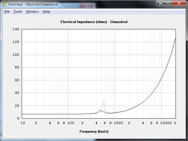
I believe the electrical impedance of the system may play a factor here too. Last week I posted some information on how the air in the horn changes the impedance of the system. IE, if you load the horn with a driver that has a low MMS, you'll see the impedance curve of the system 'flatten'. And I think that has something to do with the phase response also. (IE, if part of our phase shift is due to the resonance of the driver, then reducing that resonance via the air load in the horn will also change the phase response.
Don't even get me started on the crossover because my head might explode
Here's a post that Danley made recently that alludes to why you want a bigger compression driver to improve the phase:
Hi
I would follow the suggestions about a radius at the entry, one should avoid any straight cylindrical portions on the horn (as a hole bored through a plate is) unless it is very short in length.
You might look at a different compression driver that has a lower cutoff as in this design overlap is very desirable if you want to eliminate the crossover phase shift (like an SH-50) and have the result appear to be a single driver. Also, keep in mind that the exit wavefront on a compression driver is not always a plane wave, especially with larger format drivers. I have had very good luck with the BMS drivers which tend to have an expanding wavefront at their exit which makes the transition to the conical horn seamless..
The holes do form a “low pass” acoustic filter which is made of the mass of air in the port and the volume of air trapped under the cone body.
This is very desirable as it reduces the distortion the drivers produce.
The smaller the ports are, the lower the corner will be and also the less difference they make in the horn.
If you want to raise the mid corner F, then making the ports as short as possible (with a tapered or counter bore on the driver side) or increase the diameter is the easy path.
Have fun
Tom Danley
Danley Sound Labs
Anyways, I'll take a stab at describing how I think it's working.
Please take this post with a grain of salt. I don't understand horns even half as well as JLH, Danley, GM, and Sheerin. And my knowledge of phase is particularly weak. If in doubt, listen to those guys.
Okay, with the disclaimer out of the way, here's what I think:
If you look at the phase response of a loudspeaker, it begins to lag as we go lower in frequency. I believe this is related to the resonance of the system, but you'll want to check that. This phase lag causes the speaker to 'virtually' move backwards.
Here's a picture which I think illustrates this nicely:
An externally hosted image should be here but it was not working when we last tested it.
See how the low frequencies lag the high? And this is a VERY large distance, literally feet. I stole the pic from http://www.greenmountainaudio.com/s...peaker-phase-accuracy-and-musical-timing.html, which has some good info on phase.
In the Unity, I'd assumed that the phase shift in the horn was due to the coupling chamber in front of the midranges, but the more I research this, I believe it's due to a number of factors. The resonance of the woofer, the interaction with the coupling chamber, and even the delay introduced by traveling from various points along the diaphragm. (For instance, moving the port from the center of the woofer cone to the edge of the woofer cone changes the phase response of the loudspeaker because you increased the distance that the sound must travel.)
Long story short - you're going to need a computer to figure out the phase, but that's what Akabak and Hornresp is for.
And note, this phase shift is NOT insignificant. For instance, a quick sim shows 45 degrees of phase shift from 1200hz to 600hz. That's equivalent to moving the driver BACKWARDS by seven centimeters.
Starting to see where we're going with this? The phase change has the effect of moving the loudspeakers BACKWARDS down the horn. And for us, that's a GOOD thing, because it improves the phase response of the system. And note that if the Unity was an MTM, that phase shift would be a problem, because the woofer phase would get WORSE, instead of better. (IE, it's the combination of the woofers being in FRONT of the tweeter AND the phase shift that's key.)
One problem though - the compression driver is ALSO moving backwards as it gets close to resonance. This (might) explain why using a big beefy compression driver seems to work better. For instance, I once used a big JBL alnico in a Unity, and was able to come up with very listenable results in a matter of minutes. Doing the same with the little BMS 4540NDs and Celestions has been more challenging for me.
The solution, then, is to use the compression driver above it's resonance, if at all possible.
I know we have members on here who have been doing audio for decades, and one thing you might notice is that there are a handful of hifi loudspeakers that are absolute classics. Thiels, Vanderstiens, etc. And despite their high price and relatively low dynamic ability, they're still classics. I have a hunch that we're a lot more sensitive to timing problems than frequency and distortion problems. For instance, I've listened to JMLab speakers that cost close to $100K that were ultimately unsatisfying. But a simple Vanderstien loudspeaker is very satisfying, despite being unable to match the JMLab when it comes to dynamics. What I'm getting at here is that the Synergy speaker gives us the opportunity to have our cake and eat it too - the dynamics of a big JMLab with the satisfying 'musicality' of a Vanderstien. I think that's because of good phase response. Stereophile has published hundreds of loudspeaker measurements, and you can see the problems with phase that are endemic to 95% of the big speakers out there. Occasionally you'll see an exception, like the Dynaudio flagships.
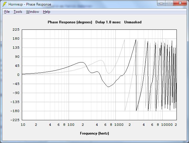
Here's a graph describing what I'm talking about. The grey line is one of the Pyle midranges that Paul's using in a sealed box. (IE, not on a horn.) The black line is the same driver on a 45 degree conical horn.
In the sealed box, there's 45 degrees of phase shift at 500hz; that's due to the resonance if I'm not mistaken. (Again, I don't really 'get' phase so I could be wrong.)
In the horn, the phase shifts a full ninety degrees, but the shift is more gradual. I'm guessing the situation is due to the number of resonances in a horn. IE, a sealed box basically has one resonance, but a horn has dozens. The phase on the horn starts to look like a sealed box from 200hz and down; I believe that is due to the horn unloading. (The conical horn in my sim has a 200hz quarter wave resonance due to a depth of 45cm.)
I believe the electrical impedance of the system may play a factor here too. Last week I posted some information on how the air in the horn changes the impedance of the system. IE, if you load the horn with a driver that has a low MMS, you'll see the impedance curve of the system 'flatten'. And I think that has something to do with the phase response also. (IE, if part of our phase shift is due to the resonance of the driver, then reducing that resonance via the air load in the horn will also change the phase response.
Don't even get me started on the crossover because my head might explode
Here's a post that Danley made recently that alludes to why you want a bigger compression driver to improve the phase:
Hi
I would follow the suggestions about a radius at the entry, one should avoid any straight cylindrical portions on the horn (as a hole bored through a plate is) unless it is very short in length.
You might look at a different compression driver that has a lower cutoff as in this design overlap is very desirable if you want to eliminate the crossover phase shift (like an SH-50) and have the result appear to be a single driver. Also, keep in mind that the exit wavefront on a compression driver is not always a plane wave, especially with larger format drivers. I have had very good luck with the BMS drivers which tend to have an expanding wavefront at their exit which makes the transition to the conical horn seamless..
The holes do form a “low pass” acoustic filter which is made of the mass of air in the port and the volume of air trapped under the cone body.
This is very desirable as it reduces the distortion the drivers produce.
The smaller the ports are, the lower the corner will be and also the less difference they make in the horn.
If you want to raise the mid corner F, then making the ports as short as possible (with a tapered or counter bore on the driver side) or increase the diameter is the easy path.
Have fun
Tom Danley
Danley Sound Labs
Last edited:
When Tom first shared that advice about using a 'bigger' compression driver with a lower FS, I only considered that such a driver would allow me to use a gentler slope in the crossover - thus a more optimal phase response. Now it seems that there is more to it than that.
Exactly. If I'm right about how this works (and I'm not certain I am), there's going to be a phase lag on *all* the drivers as you get close to resonance. From the top to the bottom.
In a lot of respects, the engineering behind this thing reminds me of what Dynaudio and Thiel does.
An externally hosted image should be here but it was not working when we last tested it.
You basically take one of these Dynaudio arrays, and fold it into a pyramid.
The horn fixes the two big complaints with the Thiel and Dynaudio speakers, which is that you have to keep your head in a vise to get good sound. (Because there are so many drivers, if you move one foot in the room the whole illusion of stereo collapses. But IF you're sitting in the right place it sounds magical.)
And obviously, the other problem being the very low dynamics and efficiency of the Dynaudio and Thiel speakers, due to the need to squeeze ultra-wide bandwidth out of every driver in the loudspeaker.
Hmm, I thought you wanted to make a SH95 concept. Using 8" for mids would make for a long three way horn. Anyway, here's what you posted:
GM
Thank you for posting that GM. One reason I'm interested in narrow vertical directivity is that I'm tired of high Q peaks and dips in the 200-600Hz region that cover small areas in space.
They are $8.39 each for a half case (30 pieces). So, it was a little over $250 for them. If you buy a full case (60 pieces) the price drops to $6.44 each.
I am down for 12 if anyone is in with me. I'm not like to do much with them in the near term, but I've been itching to try out a Synergy design, so I'd love to have them. I consider this peanuts in the grand scheme.
Josh
@JLH, about the discrepancies between hornresp and Akabak. I used your script from three years ago as a starting point. Apart from completeness of the model, would you still consider it useable? (BTW you had mentined problems with Akabak and Mmd. I have substituted Mms as it seems to work.)
It is usable, but as you noted it was totally complete. I've expanded it to included more variables. The problem I've ran into is I exceeded the maximum number of nodes that Akabak can process. I have to simulate it in two halves now. This is a pain in the butt, however it's still better than making senseless sawdust.
JLH,
Could you tell me where the number of 17m/s is based on?
Is this the number where air becomes non-linear?
If you have it, could you please point me to some information about this?
thanks,
Kees
Yes, this is were it becomes non-linear. Eminence used to have a technical white paper on their website about port velocity non-linearity. If I recall correctly, the exact number they gave was 17.12 m/s. I can't seem to find it on their website. Might try Google with key words like port velocity, air non-linearity, ect.
I am down for 12 if anyone is in with me. I'm not like to do much with them in the near term, but I've been itching to try out a Synergy design, so I'd love to have them. I consider this peanuts in the grand scheme.
Josh
I'd take 8 or 10 (couple of spares). But maybe wait a bit until JLH finishes his investigations.
Sheldon
Member
Joined 2009
Thank you, John (Patrick Bateman) for reviving the topic of the mysterious phase accuracy of the Synergy horn. Unfortunately your suggestions on the matter raise even more questions, for me at least.
I think that the folded pyramid shape of the horn helps to acoustically align the midranges to the tweeter better than conventional MTM designs. However I feel that the biggest phase distortion will be introduced by the crossover slopes and so the mechanical and electrical offset should be discussed together.
I might be wrong but I believe the phase delay at the low end of a driver is caused by the natural frequency response roll off and not the resonance. Phase should be linear in the usable bandwidth of the driver.
Regarding Paul's measurements of the Pyle driver I wonder if it's showing the effects of sealed box vs. bandpass enclosure. I've heard that bandpass ads phase distortion but I don't know what that looks like.
I'm sorry for throwing around so many guesses and no hard evidence. It would be great to hear from the experts on this topic.
You rang? (BTW - only one 'e')The 2" will be trickier. Doug Kelley
got me started on this Unity madness when he clued me in to one of his projects, which used the Dayton 2" at the throat of a Unity horn he built. Doug ended up buying Yorkvilles and has posted a few times in this thread.
But I've always thought the 2" would be a good candidate as a *midrange*, not a tweeter.
So I bought some of those on Friday too.
To use the Dayton will require some modding, as it specs aren't quite right. (Basically I intend to reduce it's back chamber, so it's FB and Q is much higher.) But it's combination of a powerful motor and a light cone may mean that it will be a better candidate than the W2-852SH from TB, which is still one of my favorite drivers for these projects.
.
Man, this was so long ago I don't remember whether we talked about this or not. It was always my intention to try the RS52 as the mid - the experiment using it as the 'tweeter' was one of those experiments that looked WAY easier than the 'real' project, and so seemed worth trying. Worked really well aside from dropping like a rock in the top octave.
Anyway you may already have this but in this thread at htguide someone actually pulled the rear chamber off and measured the RS52 t/s specs. May not be 100% accurate, but should be close enough to start plugging in to a model. I do think there may be some construction challenges with the front chamber given how much the dome protrudes, but it should be easy enough to experiment with a flat cylindrical chamber and some modeling clay to reduce the volume. I'm guessing you won't get down much below 5-600 Hz, but getting up to 2k would be worth the trade.
HTGuide Forum - RS52 tests and tweaks
I'm still in limbo on projects - trying to decide whether we're going to try to move or not. If we do move to somewhere with more space, I'm really torn between working on the U15s and joining the seeming stampede of folks trying diy versions. Tougher decision since Jdubs is selling some spare U15 horns and mids which would make it easy to get a center and still have a spare for modding/experimenting.
OTOH, the idea of a DIY version with a Neo 3 or a ribbon and the RS52s is oddly appealing.
I made an Akabak model with the Synergy horn-style ports. This is where the port is a frustrum instead of a hole. (Note the big end is on the inside.)
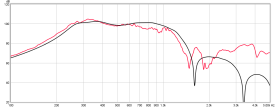
Here's Paul Spencer's measured and simulated Unity horn. This is from his blog. I am using this as an example as we have enough pictures to figure out the dimensions. The simulation was done with hornresp.
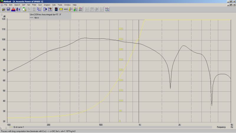
Here's an Akabak sim with a frustrum instead of a hole. I don't know if Paul's measurements used a hole or a frustrum. In the sims, I found that it doesn't make much difference until the frustrum's depth is at least 2cm or greater. This is interesting to me, as all of my Unity horns have used extraordinarily thin material. One of them even used aluminum for the mounting plate. If the sims are to be believed, there may be some advantages to using a deeper frustrum.

For instance, this sim has three changes to Paul's 60x60 Unity horn:
#1 - The frustrum is nearly 4cm deep (1.5")(!)
#2 - The midranges are slightly closer to the throat. Based on my guesstimates of the area from Paul's pics, it looks like they're a little bit further away than you would want for a 1500hz xover. For instance, to get them up that high you'd want to tap in where the throat is about 40 square cm, and in Paul's pics, I'd estimate it's about 140cm^2. As noted earlier in this thread, I think this is one of the reasons the synergy horns use a narrower coverage angle than the Unity horn. As the angle of the horn walls grows, you have move the midranges closer and closer to the compression driver, and you reach a point where you can't get them close enough.
Here's the Akabak script. Note the addition of an "api" and "apo" variable, for the frustrum. "apo" is the outer area.
When you mess around with this in Akabak, you might notice a few things:
Here's Paul Spencer's measured and simulated Unity horn. This is from his blog. I am using this as an example as we have enough pictures to figure out the dimensions. The simulation was done with hornresp.
Here's an Akabak sim with a frustrum instead of a hole. I don't know if Paul's measurements used a hole or a frustrum. In the sims, I found that it doesn't make much difference until the frustrum's depth is at least 2cm or greater. This is interesting to me, as all of my Unity horns have used extraordinarily thin material. One of them even used aluminum for the mounting plate. If the sims are to be believed, there may be some advantages to using a deeper frustrum.
For instance, this sim has three changes to Paul's 60x60 Unity horn:
#1 - The frustrum is nearly 4cm deep (1.5")(!)
#2 - The midranges are slightly closer to the throat. Based on my guesstimates of the area from Paul's pics, it looks like they're a little bit further away than you would want for a 1500hz xover. For instance, to get them up that high you'd want to tap in where the throat is about 40 square cm, and in Paul's pics, I'd estimate it's about 140cm^2. As noted earlier in this thread, I think this is one of the reasons the synergy horns use a narrower coverage angle than the Unity horn. As the angle of the horn walls grows, you have move the midranges closer and closer to the compression driver, and you reach a point where you can't get them close enough.
Here's the Akabak script. Note the addition of an "api" and "apo" variable, for the frustrum. "apo" is the outer area.
When you mess around with this in Akabak, you might notice a few things:
- If the midranges are very close to the throat, you need small and shallow frustrums. Conversely, as you move further away, you need wider and deeper frustrums. If this observation is true, then moving the midranges too close to the compression driver may limit the SPL of the system. (IE, there seems to be a 'sweet' spot, not too close and not too far from the throat.)
- I think there's a correlation between the size of the frustrums and the diameter of the throat where it taps in. IE, if the throat is relatively large the frustrums need to be large too. I'm guessing the continuity between the frustrum and the horn is important.
- To a great extent, we are modelling a compression driver here. To *really* do this justice, we should probably break up the midranges into a 'real' compression driver model. I took a stab at doing just this, based on a PDF file named 'winderm.pdf' that's freely available.
Code:
System 'S1'

|DATA EXPORTED FROM HORNRESP - RESONANCES NOT MASKED

|COMMENT: redspade Unity horn

|========================================================================================================

|REQUIRED AKABAK SETTINGS:

|File > Preferences > Physical system constants:

|Sound velocity c = 344m/s
|Medium density rho = 1.205kg/m3

|Sum > Acoustic power:

|Frequency range = 10Hz to 20kHz
|Points = 533
|Input voltage = 2.83V rms
|Integration = 2Pi-sr
|Integration steps = 1 degree ... 1 degree
|Integration method = Cross

|========================================================================================================

Def_Const |Hornresp Input Parameter Values
{
|Length, area and volume values converted to metres, square metres and cubic metres:

S1  =     5.07e-4;  |Horn segment 1 throat area (sq m)
S2  =   100.00e-4;  |Horn segment 1 mouth area and horn segment 2 throat area (sq m)
S3  =  1000.00e-4;  |Horn segment 2 mouth area and horn segment 3 throat area (sq m)
S4  =  2116.00e-4;  |Horn segment 3 mouth area and horn segment 4 throat area (sq m)
S5  =  3716.00e-4;  |Horn segment 4 mouth area (sq m)

L12 =     6.20e-2;  |Horn segment 1 axial length (m)
L23 =    20.00e-2;  |Horn segment 2 axial length (m)
L34 =    11.00e-2;  |Horn segment 3 axial length (m)
L45 =    13.00e-2;  |Horn segment 4 axial length (m)

Vrc =     1.00e-3;  |Rear chamber volume (cubic m)
Lrc =     1.27e-2;  |Rear chamber average length (m)

Apo =    20.35e-4;  |Throat chamber port cross-sectional area - outside(sq m)
Api =    160.00e-4;  |Throat chamber port cross-sectional area - inside (sq m)
Lpt =     3.81e-2;  |Throat chamber port tube length (m)

Vtc =   180.00e-6;  |Throat chamber volume (cubic m)
Atc =   296.00e-4;  |Throat chamber cross-sectional area (sq m)

|Parameter Conversions:

Sd  = 296.00e-4;  |Total diaphragm area for 2 series x 2 parallel drivers (sq m)

Arc = Vrc / Lrc;

Ltc = Vtc / Atc;
}
|========================================================================================================

|Network node numbers for this offset driver horn system:

|     0-Voltage-1
|               |
|4-Chamber-5-Driver-6-Chamber-7-Port-
|                                    |
|                          8-Segment-9-Segment-10-Segment-11-Segment-12-Radiator

|========================================================================================================

Def_Driver 'Driver'

  Sd=74.00cm2
  Bl=3.60Tm
  Cms=8.96E-04m/N
  Rms=0.20Ns/m
  fs=107.9395Hz  |Mmd = 2.06g not recognised by AkAbak, fs calculated and used instead
  Le=1.00mH
  Re=6.70ohm
  ExpoLe=1

System 'System'

  Driver Def='Driver''Driver 11'
    Node=1=13=5=6
  Driver Def='Driver''Driver 12'
    Node=13=0=5=6
  Driver Def='Driver''Driver 21'
    Node=1=23=5=6
  Driver Def='Driver''Driver 22'
    Node=23=0=5=6

  Duct 'Rear chamber'
    Node=4=5
    SD={Arc}
    Len={Lrc}
    Visc=0

  Duct 'Throat chamber'
    Node=6=7
    SD={Atc}
    Len={Ltc}
    Visc=0

  Waveguide 'Throat adaptor'
    Node=9=7
    STh={Apo}
    SMo={Api}
    Len={Lpt}
    Conical

  Waveguide 'Horn segment 1'
    Node=8=9
    STh={S1}
    SMo={S2}
    Len={L12}
    Conical

  Waveguide 'Horn segment 2'
    Node=9=10
    STh={S2}
    SMo={S3}
    Len={L23}
    Conical

  Waveguide 'Horn segment 3'
    Node=10=11
    STh={S3}
    SMo={S4}
    Len={L34}
    Conical

  Waveguide 'Horn segment 4'
    Node=11=12
    STh={S4}
    SMo={S5}
    Len={L45}
    Conical

  Radiator 'Horn mouth'
    Node=12
SD={S5}As noted earlier in this thread, I think this is one of the reasons the synergy horns use a narrower coverage angle than the Unity horn. As the angle of the horn walls grows, you have move the midranges closer and closer to the compression driver, and you reach a point where you can't get them close enough.
I think you got that backwards. The local area of expansion (i.e. the flare rate) of a conical horn is higher near the throat. As you move closer to the mouth, the flare rate lowers. If you move the midranges close to the throat, then you'll never get them to play low enough in frequency to meet up with the woofers. It is more like a three way tug-of-war with the factors being:
1.)Cross sectional area the midranges tap into
2.)Distance from the throat the midranges tap into
3.)The local area of expansion the midranges tap into
If the cross sectional area the midranges tap into is has a circumference equal to, or less than the lowest frequency played by the compression driver the ports will cause interference and frequency response abnormally.
If the distance from the throat that the midranges tap into is too far away you get a half wave cancellation notch before the midrange's high frequency output can meet up with the compression driver's lowest frequency output.
If the local area of expansion (i.e. flare rate) is too high, then you will never get the midranges to play low enough in frequency. The flare rate controls where the midranges will cutoff in the low end.
John,
My statement was in regards to the coverage angle of the horn, not the flare rate. For instance, let's say you have a Unity horn with a sixty degree coverage angle, and one side is 40cm. Due to the sixty degree coverage angle, all sides are 40cm.*
Now take the exact same horn, and reduce the coverage angle from sixty degrees to forty degrees. While the mouth size is exactly the same, the sides of the horn have grown to 58.5cm. And those longer sides give your more room to mount the midranges.
Basically, reducing the horns coverage angle by 33% has increased the length of the horn sides by 46.25%. And that increase in the horn sides gives us additional leeway in mounting the midranges.
The key is that the flare rate at the mouth is unchanged, because the mouth size is identical. All that's changed is the coverage angle, and the amount of space we can dedicate to mounting the midranges.
Of course, everything else in your post is true. I think tweaking the coverage angle just allows you a little leeway in finding the perfect location for mounting the midranges.
* All of these calculations are based on a two dimensional horn. In the real world, the numbers will be a bit different because we're working with a three-dimensional pyramid, not a two-dimensional triangle.
Last edited:
John,
My statement was in regards to the coverage angle of the horn, not the flare rate. For instance, let's say you have a Unity horn with a sixty degree coverage angle, and one side is 40cm. Due to the sixty degree coverage angle, all sides are 40cm.*
Thanks for clearing that up, I didn't quite follow you the first time.
The key is that the flare rate at the mouth is unchanged, because the mouth size is identical. All that's changed is the coverage angle, and the amount of space we can dedicate to mounting the midranges.
Incorrect. Since the length changed so did the flare rate along the horn. Local flare rate is determined by the amount of length per the halving, or doubling of cross sectional area. Since your horn is longer overall, but has the same mouth area, the length to halve or double will be longer resulting in a lower flare rate.
I do agree that changing the coverage angle can be a helpful tool. 50 X 30 seems to be a pretty good sweet spot for many of my models. My goal has always been for a 60 X 40 horn.
- Home
- Loudspeakers
- Multi-Way
- Suitable midrange cone, for bandpass mid in Unity horn.