Have you simulated anything in hornresp or akabak?
I've simulated in hornresp but haven't tried akabak.
Hornresp simulating the mid showed a rising phase with a 45 degree shift at 770hz (relative to 0 at 600hz). I measured a 30 degree shift so I'd say this matches my measurements of the mids reasonably well.
Thinking it through again, perhaps this is enough to explain my discrepancy in the distance measured.. 135 degrees at 770hz would be 6.6inches which is starting to sound more plausible based on the physical separation.
Please read entire JLH posts, its been beaten over and over, its not just about 1/4 wavelength, but tap circumference and local flare rate come into play a swell. Spreadsheet already available made by Bill Waslo over diysoundgroup forum. Happy building.
Hi panjilara,
May be I was not clear in my question. I know that I probably need to read tons of pages, however I was merely trying to put in into one post and see if I got it right (remember, I am learning here and so far as described).
I went to the doctor the other day and told him it was getting harder and harder to get asleep at night. So he asked me "what have you been doing lately.." and I told him of my hobby, the Tapped & Untity / Synergy Horn and my wish to build a good set as a small and portable PA. "aaah hah....." he said, "my dear Frans, you are suffering a severe information overload....."
 "So what can I do about that, I need to read stacks of pages to figure it out....
  " I asked. He answered "Well maybe start to shift the main issue of those Unity thingies.... from the gory details and nail them down one by one, so you can focus on it issue by issue...." "From there on you could work out the whole picture, together with other horn fanatics". Now that sounded as a good advise, I went home, got to sleep and so here I am with the first "issues". Where to put the taps and how big a tap. The circumference is partly covered in this version (if y know the center and the side of a circle I know the circumference).
 I saw the excel sheet of Bill Waslo, this DOES NOT tell me where to tap. He talks briefly in the "How to" tab of the sheet, but only mentions a figure, god knows where that came from. You see panjilara, that's my point here, I can't find the reasoning behind a result shown in most posts.
I also have links to a number of other posts and threads, so far NON OF THEM exactly tell me HOW they got the tap points, other then "copy-cat" or estimate.
That's why I ended up with my post.
If you can tell me WHERE it is described, I would be VERY thankful. If you don't know or otherwise, no hard feelings, I will try to get there anyway.
MAIN QUESTION: is my way of calculating (limited to where to tap and how big a tap) the way to go???.
I do need to get deeper into the size and shape of the tap, the part of the tap that does not need to get flared (I read that it's about 3 mm that you can leave "not flared", but NO clue why) and flare of the tap at the driver side (seen some nice examples of solid woodworking and a smooth transition over some area, but NO details NOR reasoning. Next of course shape and size of the horn, crossovers etc.
kind regards,
Frans Wessels
[1] The unity horn patent suggests a cute trick for measuring the "true" distance between the high and the mid. I run a frequency response with both drivers (no crossover) and then invert polarity of one and run it again. There is a big dip where they are 180 deg out of phase, in my case this is at 770 Hz. That corresponds to a physical separation of 8.8 inches between the drivers which seems way too large! The mids are ported into the horn a little over 3.5 inches down the axis from CD screen where the horn is 3 inches tall. Even measuring from the back of the CD to the centerline of the mid I can't come up with more than maybe 6.5 inches of separation.
Thanks is advance for any advice
My guess is that, the dip you have @770Hz is the 180 phase shift from the mid itself when it bounces of the CD and returns downstream the horn...
/Thomas
If you found 770 Hz as the point where there is a big dip, measured with 1 driver reversed polarity, than it makes perfectly sense (or I don't get it..);
In meters, wavelength = c / f gives 344/770 = 0,4467 meters = 44,67 cm = 17,58 inches. 180 degrees = ½ wavelength = 8,8 inches. So the out of phase (dip) point is 8,8 inches.
So you measurements are correct. Question is, would that mean that you need to shift your tap point to 4,4 inches (¼ wavelength from 770 Hz for your driver combination??). Now that still sounds "far away" compared to photo's of the real deal.
The fact that you have them tapped at 3,5 inch from the CD may be will not influence your measurement....
To be honest, I don't know, but this could be a way (following the patent you read) to figure out crossover points.
770 Hz sounds low for a crossover, the more I think of this, the more I get the feeling it will not tell you where to tap, but it tell's you where in the current horn you are 180 out of phase. So forget about it....???...
ORRR--
Since you have measured without crossover, IT IS the IDEAL crossover point for the combination of driver and horn you use. Still, 770 Hz is very low for a CD to survive some nice AC/DC performance. Did you find other dips higher up, which could make the ideal crossover ???
kind regards,
Frans Wessels
Last edited:
Additional thoughts
Adding the path length from the voice-coil of the mid driver (6 " driver is almost 1" path) to the tap point comes very close to 8.8" = ½ wavelength. THAT could also be a reason. Tap-point = 3,5" + additional-path 1" = 4,5" as ¼ wavelength (or 9" ½ wavelength).
ALSO explains why you did find hardly any difference in moving the driver under the fix tap point. The "driver path" behind the tappoint is almost the same from any angle)
You said you did find other dip's around 1KHz, may be that's the one to use. 1KHz gives 3,3" as ¼ wavelength minus 1" driver path = 2,3" tap point???
kind regards,
Frans Wessels
Last edited:
I don't think it's fair that JLH has to repeat himself over and over.... - so I'll just copy-paste what he has already written once or twice or more...
I'll go over this one last time. To reach your desired high frequency output of the mids the following must be true:
1.) The circumference of the cross sectional area must be equal to or less than 1 wave length of the highest frequency.
2.) The distance between the acoustical center of the compression driver and the tap point must be one half a wave length or less.
In most cases people are getting the mids close (satisfying number 2), but fail to ensure the area is correct.
Everyone needs to re-read the Synergy horn patent again.
*********************************************
The ideal balance is when the circumference of the area the mids tap into is equal to one wave length of the highest frequency, and the distance between the acoustical center of compression driver and mids is half a wave length of the highest frequency. In your case of 1.5KHz this would mean that you want to tap the mids into the horn with an area of 41.65cm^2 that is 11.42cm from the acoustical center of the compression driver.
***********************************************
Let’s use an example where we are crossing over a compression driver at 1200Hz. At this frequency the full wave length is about 28.56cm long. If we take this compression driver and load it into a conical horn, the horn will stop providing a load to the driver around where it expands to 64.91cm^2. Once you expand to beyond an area that is greater than one full wave length, the driver can no longer exert any pressure against the horn walls. (The juvenile analogy I use is it becomes like throwing a hotdog down a hallway.) Now take this a step further and use a square/rectangular horn instead of an axis symmetrical horn. The pressure in the corners drops even sooner than the flat side walls. Tuck your entry ports in the corners, and there is almost zero chance of them interfering with the compression driver’s output. To fully ensure you won’t get interference, you want to tap the mids in where the area is slightly larger than 64.91cm^2. We design to have a small gap between when the compression driver unloads, and when the mids turn on. There will be enough summing at the crossover point to provide a flat power response. There should not be a dip in response.
*******************************************
What I aim for is having the cancellation notch slightly lower in frequency than my crossover point for the mid. (e.g. Crossover is 1st order lowpass at 1300Hz, notch at around 1200Hz to 1250Hz.) You want the acoustical cancellation notch doing most of the filtering work. If you place your crossover point too close to the notch, you end up with a peak in response once it sums with the compression driver and its crossover. The 1st order lowpass on the mid is there for phase shifting, and to filter out the mids high frequencies once it rebounds from the notch an octave above.
Thanks again, John
so Hmmmf, how did your synergy turn out?
regarding bullet 2) in your post. The phrasing is a little vague. Would it be more precise to say: The round trip distance between the acoustical center of the compression driver and the tap point must be one half a wave length or less at the crossover frequency
Note to Wae: the acoustical center of the CD can be a significant distance back from the throat of the horn: around 6 cm for a BMS4550 and around 3 cm for DEC250. JLH has posted those numbers somewhere in this thread
Do I understand it correctly when you say "round trip distance" you mean ½ wavelength, so actually ¼ wavelength real distance??? Also, there is no minimum distance is there?
OK, for the high frequency it look alike worthwhile taking this into the calculation.
thanks for the details.
kind regards,
Frans Wessels.
Frans,
You are correct that my spreadsheet doesn't tell you where to put the side ports. What it does is calculate the dimensional values for you to put into HornResponse, based on a horn radiation angle and port distance from tweeter diaphragm that you choose. Then in HR, you enter your drivers' parameters and adjust, by trial and error, to see what kind of response and efficiency you would get with all those values. Trial and error with the simulation, see if the driver could work ok, try different volumes and areas and lengths for port and chambers, see if that port position coild be used (if not, change that back in Synergycalc, to get new dimensional values for HR again, investigate and repeat). It's not a tool to give you the answer directly, but an aid to getting buildable values to try in HornResponse. Then when you have something that looks promising in HornResponse, SynergyCalc will calculate the board sizea and angles to build it.
You are correct that my spreadsheet doesn't tell you where to put the side ports. What it does is calculate the dimensional values for you to put into HornResponse, based on a horn radiation angle and port distance from tweeter diaphragm that you choose. Then in HR, you enter your drivers' parameters and adjust, by trial and error, to see what kind of response and efficiency you would get with all those values. Trial and error with the simulation, see if the driver could work ok, try different volumes and areas and lengths for port and chambers, see if that port position coild be used (if not, change that back in Synergycalc, to get new dimensional values for HR again, investigate and repeat). It's not a tool to give you the answer directly, but an aid to getting buildable values to try in HornResponse. Then when you have something that looks promising in HornResponse, SynergyCalc will calculate the board sizea and angles to build it.
Bill,
Thanks for the reply and the back grounds on this sheet. Very clever piece of excel programming. I wasn't at that stage yet, I couldn't get my hands behind the choice of mids and the tap points. I have the sheet available once I want to start building. Also did not really understand how to put the parameters of 4 driver into Hornresp. Just ran into this link:
http://www.diyaudio.com/forums/multi-way/244503-synergy-bms-4550-visaton-m10-5.html
It goed into nice details on how to use Hornresp and also your excel sheet.
I'll keep reading.
What is the latest version of the spreadsheets? I have Synergy Valc V5-2.
Have you ever thought on making a "first guess button" to start using Hornresp?
Kind regards,
Frans Wessels
Last edited:
I'm still in the design phase. It's a 2-way (Faital HF 146 & Faital 8FE200). It's progressing slowly, but hopefully I'll have a full working model in the near future...so Hmmmf, how did your synergy turn out?
This corresponds to the CD/mid relationship, not the mid bouncing of the CD center, if that's what you mean?regarding bullet 2) in your post. The phrasing is a little vague. Would it be more precise to say: The round trip distance between the acoustical center of the compression driver and the tap point must be one half a wave length or less at the crossover frequency
Note to Wae: the acoustical center of the CD can be a significant distance back from the throat of the horn: around 6 cm for a BMS4550 and around 3 cm for DEC250. JLH has posted those numbers somewhere in this thread
Exactly! The acoustic center of the Faital HF-146 lies 35.5mm from the CD exit. One has to take this into account when modeling.
I would like to encourage all of you guys who has not yet aquired the skills of AkAbak, to do so. It's really superior to Hornresp. when it comes to Synergy horn modeling.
/Thomas
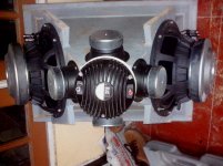
My "slow as hell" project
Looking good!
...At least you're at the wood chopping stage
My guess is that, the dip you have @770Hz is the 180 phase shift from the mid itself when it bounces of the CD and returns downstream the horn...
The dip @770 is when I reverse the phase of the mid relative to the phase of the compression driver. A dip due to a half-wavelength reflection would depend primarily on the horn geometry and be there regardless of the phase of the mid (and would probably be largely the same regardless of whether the CD was turned on or not, although someone mentioned that having the diaphragm wired up to the amp might damp the reflection in some way).
Adding the path length from the voice-coil of the mid driver (6 " driver is almost 1" path) to the tap point comes very close to 8.8" = ½ wavelength. THAT could also be a reason. Tap-point = 3,5" + additional-path 1" = 4,5" as ¼ wavelength (or 9" ½ wavelength).
Hi Frank -- The cancelation I was talking about is from swapping the wiring on the mid driver to reverse the phase, not from throat reflection. If the high and mid are separated by a half wavelength then the will destructively interfere. 3.5" along the waveguide plus additional 2-3" to account for offsets of the acoustical centers for both the compression driver and the mid driver still doesn't add up to 8.8". My thinking now is that it has to do with additional phase shift of the drivers themselves along with any bandpass phase effects of porting the mids that accounts for the additional delay of the mid response... this would cause them to interfere at a lower than expected frequency when wired out of phase.
I'm rebuilding a cleaner version and will post again once I have a chance to redo the measurements.
Would still love to hear if anyone else has replicated this kind of experiment on their own builds.
- Home
- Loudspeakers
- Multi-Way
- Suitable midrange cone, for bandpass mid in Unity horn.