is the Beta-6A a new Eminence creation ?
might be a good 1khz driver
Its fairly new. It is a beast in a small midbass tapped horn.
I wasn't sure where best to post/ask about this so I came back to the mother thread.
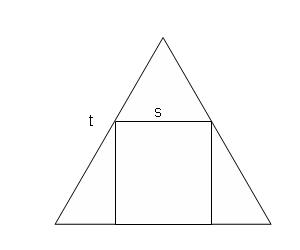
Has anyone proceeded with the room corner synergy horn concept? i.e. a three sided horn at the floor/wall or ceiling/wall.
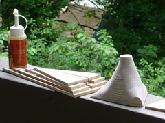
After building a typical square horn prototype with my dad and negotiating WAF I've decided that this will definitely be my path.
I hate power tools so would like to simplify the cuts. They is not a lot simpler than three pieces of wood glued together. No mitered/angled cuts required for a three sided horn.
Prototyping is a breeze too - just grab a cardboard box.
I'm been messing around with a headphone driver (Fostex T50rp) as the tweeter.
It's rated for 15 W, I believe. Works pretty well above 2000 Hz.
Final design will likely use a hand made AMT. (Have a prototype working but am slower than bandsei and solhaga as I keep having to move cities! It's difficult to set up a workspace.)
As a physicist, I can't see a great deal of compromises with such a corner design. The 'sound at floor level' is not much of an issue since the triangular horn could just as well be raised ear height by sacrificing one side. I'll be able to get away with a pretty small horn by terminating it well with the room and will end up with the max possible LF from my mids.
HF will require some care but I don't expect any major hiccups below say 10 kHz. Last year I was living with a trio of up firing 3"er flooders and actually enjoyed the lack of direct HF but flat power response.
Anyway, just thought I'd remind everyone of the idea.
Has anyone proceeded with the room corner synergy horn concept? i.e. a three sided horn at the floor/wall or ceiling/wall.
After building a typical square horn prototype with my dad and negotiating WAF I've decided that this will definitely be my path.
I hate power tools so would like to simplify the cuts. They is not a lot simpler than three pieces of wood glued together. No mitered/angled cuts required for a three sided horn.
Prototyping is a breeze too - just grab a cardboard box.
An externally hosted image should be here but it was not working when we last tested it.
I'm been messing around with a headphone driver (Fostex T50rp) as the tweeter.
An externally hosted image should be here but it was not working when we last tested it.
It's rated for 15 W, I believe. Works pretty well above 2000 Hz.
Final design will likely use a hand made AMT. (Have a prototype working but am slower than bandsei and solhaga as I keep having to move cities! It's difficult to set up a workspace.)
As a physicist, I can't see a great deal of compromises with such a corner design. The 'sound at floor level' is not much of an issue since the triangular horn could just as well be raised ear height by sacrificing one side. I'll be able to get away with a pretty small horn by terminating it well with the room and will end up with the max possible LF from my mids.
HF will require some care but I don't expect any major hiccups below say 10 kHz. Last year I was living with a trio of up firing 3"er flooders and actually enjoyed the lack of direct HF but flat power response.
Anyway, just thought I'd remind everyone of the idea.
Boom!
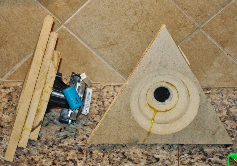
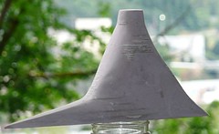
This worked exactly like it should. Your basic conical horn. It was easy to build and it was effective. To make it perfect you'd want to use an oblate spheroidal curve for a better transition from the throat to mouth. This is easy to do; just add one more sheet of MDF between the throat and the waveguide to smooth the transition from throat to horn.
Prior to that one, I made some attempts to transition from a circular throat to a three-sided horn. All of them worked like crap. The problem is the high frequencies. 5khz is 6.8cm long. Due to that short length, a pathlength difference of just 1.7cm will screw up your response.
So a three sided triangle has much much larger pathlength problems than a square or a rectangle. A round horn has no pathlength problems at all, but it has some problems of it's own. (resonance.)
I hate to be a downer, but a rectangular horn works pretty well, and one that's the golden ratio is even better. (Good polar response, spreads out the resonances that you get with a square or a round horn.)
But all is not lost
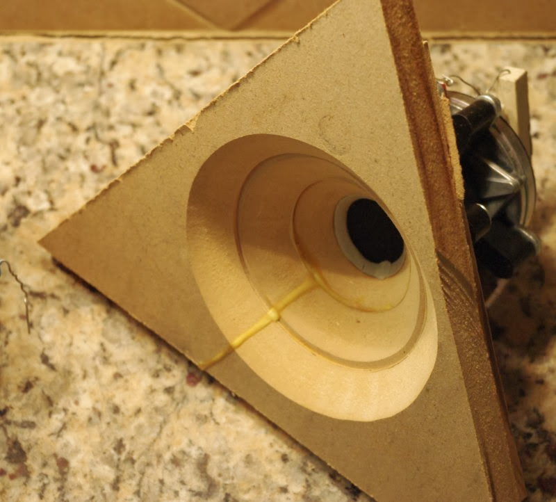
Because you can basically have your cake and eat it too. You can put a circle in a triangle, as I did in the first pic. And then you have the best of both worlds. You have a high frequency horn with good polar response for the first three or four inches, and then you transition to a three or four sided horn for the rest.
Even the Danley horns have a slooooow transition from circular to square.
This worked exactly like it should. Your basic conical horn. It was easy to build and it was effective. To make it perfect you'd want to use an oblate spheroidal curve for a better transition from the throat to mouth. This is easy to do; just add one more sheet of MDF between the throat and the waveguide to smooth the transition from throat to horn.
Prior to that one, I made some attempts to transition from a circular throat to a three-sided horn. All of them worked like crap. The problem is the high frequencies. 5khz is 6.8cm long. Due to that short length, a pathlength difference of just 1.7cm will screw up your response.
So a three sided triangle has much much larger pathlength problems than a square or a rectangle. A round horn has no pathlength problems at all, but it has some problems of it's own. (resonance.)
I hate to be a downer, but a rectangular horn works pretty well, and one that's the golden ratio is even better. (Good polar response, spreads out the resonances that you get with a square or a round horn.)
But all is not lost
Because you can basically have your cake and eat it too. You can put a circle in a triangle, as I did in the first pic. And then you have the best of both worlds. You have a high frequency horn with good polar response for the first three or four inches, and then you transition to a three or four sided horn for the rest.
Even the Danley horns have a slooooow transition from circular to square.
The issue of the throat is the reason that I intend to use a planar driver and avoid having to transition from round to triangular. If I expose only a portion of the face of my planar (or even better an AMT) then I think that I can get away with very little in the way of rounding.
My expectation is that the simple construction of a triangular horn will allow for tight tolerances. If I can control things to the level of 0.5 cm then my polars will at least be smooth, if not 100% even.
Coherence up to 5-7 kHz would be enough to sound great, I think. Circumaural headphones can sound awesome, yet have a different response > 7 kHz every time that you put them on. Let's say that I'm aiming for unity horn within the HRTF range.
I tested another cardboard box setup with the tweeter occupying one wall only. This config has the best chance of achieving perfect boundary conditions (i.e. a wave guide) and should have the same physical consequences as a tweeter of twice the dimensions aligned parallel to a wall. In this case I would suppose that I could either shade the part of the tweeter furthest from the throat with foam, or else make the horn walls absorptive in order to reduce interference > 5 kHz.
For my own benefit, I need to accept that I don't have the wood skills to build the standard horn, that my dad is not safe enough when cutting wood, and that I'll soon be in yet another state in an apartment without a workshop.
If the treble response is not good enough with the simplest construction then I can try the cake-and-eat-it-too scenario at the throat.
And if the project fails I'll convert it to a Pluto style speaker.
I just had a minute to do make some rough and ready measurements of the Fostex T50rp + cardboard box triangular horn shown above.
Holding the box with my legs I took a bunch of measurements with an uncalibrated WM61a mic, moving it around about 10-15 cm from the throat. Don't have a turntable setup right now.
First up I have some unnormalized plots -
and now normalized to the first measurements (which is not necessarily exactly on-axis -
I would say that it's holding up pretty well in the range I'm interested in (< 10 kHz. The interference effects should be less severe further into the room (less steep angles of incidence from the diaphragm and horn walls).
I think that exposing only part of the planar driver might be causing a bit of a bandpass filter. I'll now check how it looks when I mount the driver to one side of the triangular pyramid only.
Holding the box with my legs I took a bunch of measurements with an uncalibrated WM61a mic, moving it around about 10-15 cm from the throat. Don't have a turntable setup right now.
First up I have some unnormalized plots -
An externally hosted image should be here but it was not working when we last tested it.
and now normalized to the first measurements (which is not necessarily exactly on-axis -
An externally hosted image should be here but it was not working when we last tested it.
I would say that it's holding up pretty well in the range I'm interested in (< 10 kHz. The interference effects should be less severe further into the room (less steep angles of incidence from the diaphragm and horn walls).
I think that exposing only part of the planar driver might be causing a bit of a bandpass filter. I'll now check how it looks when I mount the driver to one side of the triangular pyramid only.
Last edited:
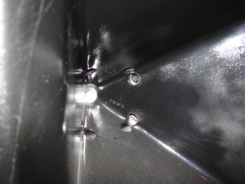
Here are some more rough measurements, this time with the planar tweeter flush on one of the walls-
These measurements rough from roughly along the horn where the 'walls' meet in the direction the tweeter faces to 90 degrees off axis. The top one is with the mic sitting on the driver. I forgot to mention before that these are 1/12 octave smoothed with a 2ms gate.
Deviations after 4 khz are about what you would expect for the effective ~3.5-4 cm exposed driver. The center to center spacing of the driver and it's 'mirror' is about a half wavelength at 4 kHz.
I also quickly tried putting some chamois on some of the driver to shade it's HF away from the walls.
I then get something like this
The 90 degree dip is less severe in this case.
I can't say how consistent I was with my distance from the driver when holding the mic free hand... In addition, orientation of the mic capsule probably affects the top octave, in addition.
Tomorrow I'm going to be in my dad's workshop - hopefully we'll construct an such a horn from MDF and I'll make some more serious measurements. My rough measurements only allow for a vague qualitative insight thus far.
I think that either of my configurations (tweeter flush with one wall vs a cutaway at the throat) could provide acceptable sound quality.
An AMT with the 'cutaway' version could be pretty nice, since I'd be able to spread out the pleat resonances with the triangular opening.
An externally hosted image should be here but it was not working when we last tested it.
These measurements rough from roughly along the horn where the 'walls' meet in the direction the tweeter faces to 90 degrees off axis. The top one is with the mic sitting on the driver. I forgot to mention before that these are 1/12 octave smoothed with a 2ms gate.
An externally hosted image should be here but it was not working when we last tested it.
Deviations after 4 khz are about what you would expect for the effective ~3.5-4 cm exposed driver. The center to center spacing of the driver and it's 'mirror' is about a half wavelength at 4 kHz.
I also quickly tried putting some chamois on some of the driver to shade it's HF away from the walls.
An externally hosted image should be here but it was not working when we last tested it.
I then get something like this
An externally hosted image should be here but it was not working when we last tested it.
The 90 degree dip is less severe in this case.
I can't say how consistent I was with my distance from the driver when holding the mic free hand... In addition, orientation of the mic capsule probably affects the top octave, in addition.
Tomorrow I'm going to be in my dad's workshop - hopefully we'll construct an such a horn from MDF and I'll make some more serious measurements. My rough measurements only allow for a vague qualitative insight thus far.
I think that either of my configurations (tweeter flush with one wall vs a cutaway at the throat) could provide acceptable sound quality.
An AMT with the 'cutaway' version could be pretty nice, since I'd be able to spread out the pleat resonances with the triangular opening.
Akabak-question:
I tried building on some of the many models here to see if I could understand how the Synergy horn works. I wanted to construct the whole model in Akabak, simulate the responses from each individual segment (CD, midranges, and woofers later on), import the responses into Charlie Laub´s Active Crossover Designer, and see if miniDSP (or the Najda board) could do the crossover to arrive at flat response and phase.
I used JLH´s model of the Visaton M10 midranges (cavities and ducts), and a DE250 model found here: Akabak script for DE250 compression driver - Speakerplans.com Forums).
There seems to be two ways (or more) in Akabak to disable the midranges while leaving the front chamber and ducts in place to get the resonances from these. The first is to delete the Driver section for the midranges, while leaving the rest in place. The second would be to leave the drivers in place, and connect them from positive (in this case node 2 after the output impedance of the amplifier) to a "dummy node" that doesn´t lead anywhere.
These two approaches give very different results. It seems like a non-connected driver will have its own resonance, and therefore modify the cavities and ports in for the midranges, leading the a very different notch frequency for the CD.
My question is if leaving the driver connected to a dummy node will give the correct results, or should I try to simulate some kind of amplifier connection? i.e. will a non-connected driver behave differently than one that is connected by receives no signal from the amplifier?
Here is the variant with the driver connected to a dummy node:

And here is the one with the driver removed:
I tried building on some of the many models here to see if I could understand how the Synergy horn works. I wanted to construct the whole model in Akabak, simulate the responses from each individual segment (CD, midranges, and woofers later on), import the responses into Charlie Laub´s Active Crossover Designer, and see if miniDSP (or the Najda board) could do the crossover to arrive at flat response and phase.
I used JLH´s model of the Visaton M10 midranges (cavities and ducts), and a DE250 model found here: Akabak script for DE250 compression driver - Speakerplans.com Forums).
There seems to be two ways (or more) in Akabak to disable the midranges while leaving the front chamber and ducts in place to get the resonances from these. The first is to delete the Driver section for the midranges, while leaving the rest in place. The second would be to leave the drivers in place, and connect them from positive (in this case node 2 after the output impedance of the amplifier) to a "dummy node" that doesn´t lead anywhere.
These two approaches give very different results. It seems like a non-connected driver will have its own resonance, and therefore modify the cavities and ports in for the midranges, leading the a very different notch frequency for the CD.
My question is if leaving the driver connected to a dummy node will give the correct results, or should I try to simulate some kind of amplifier connection? i.e. will a non-connected driver behave differently than one that is connected by receives no signal from the amplifier?
Here is the variant with the driver connected to a dummy node:
And here is the one with the driver removed:
Attachments

I am experimenting with a rather large synergy horn, 250hz horizontal directivity, 84°×54° using the B&C 5MDN38 and DE250, BMS 4550 or faital HF146.
My first prototype is quite promising, although I only use one mid. The mid entry hole is 40×13mm starting about 60mm and ending at 95mm from the CD mesh along the horn axis. I will try different placements and shapes of the entry hole to see how it alters the response around 1 khz. The mid chamber is ~0,6 liters minus the driver.
I dont know if it has been discussed but I assume that the mid entry holes should not have a distance > λ ∕ 4 amongst themselves. Or is this only a necessary condition for the CD-mid distance?
Assume I aim for a crossover frequency of 1,1-1,2khz, the distance between the diagonally placed mid entry holes should be no more than 75 mm from each other? c-c distance or distance between the farthest edges?
Regarding crossover frequencies, should the mid be tailored to roll of acoustically at intended frequencies or is desirable to have somewhat of an overlap and then cross electrically?
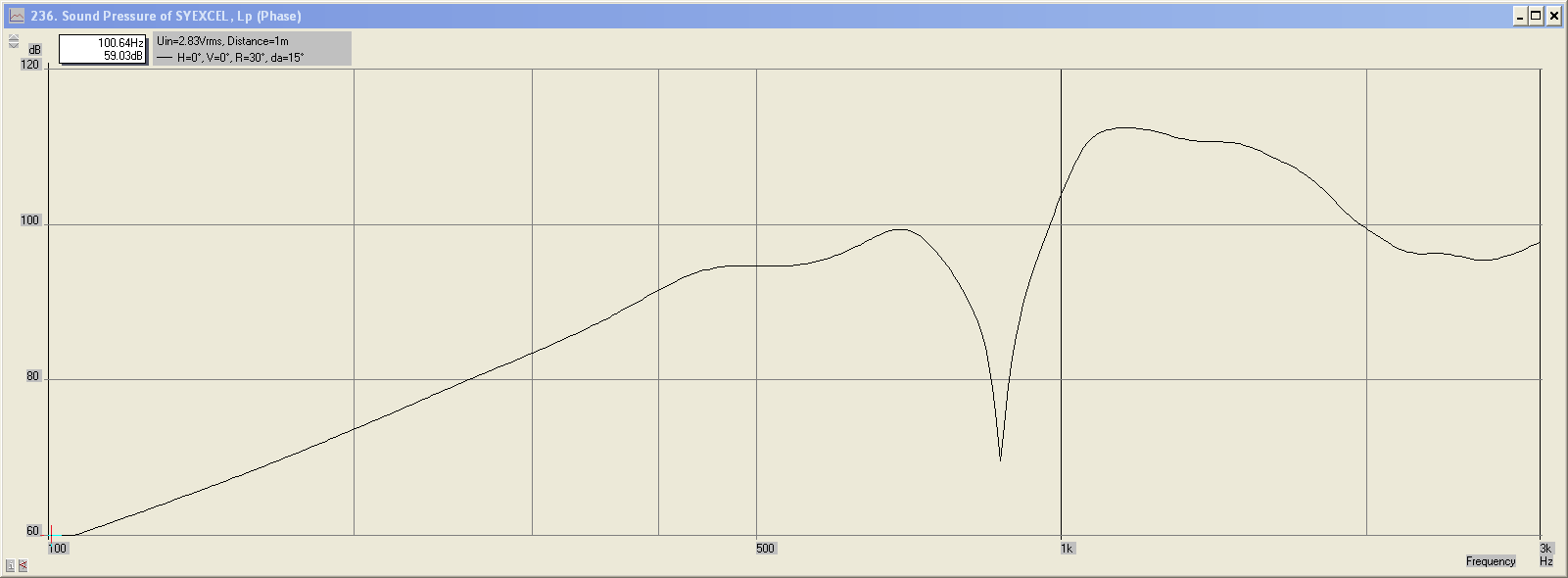
This is taken about 1m from horn mouth w. smoothing

This is average from 0,5m, 1m and 2m, no smoothing

With DE250, no mid LP filter 200hz HP, 1,1khz HP DE250, no delay/phase adjustment


My first prototype is quite promising, although I only use one mid. The mid entry hole is 40×13mm starting about 60mm and ending at 95mm from the CD mesh along the horn axis. I will try different placements and shapes of the entry hole to see how it alters the response around 1 khz. The mid chamber is ~0,6 liters minus the driver.
I dont know if it has been discussed but I assume that the mid entry holes should not have a distance > λ ∕ 4 amongst themselves. Or is this only a necessary condition for the CD-mid distance?
Assume I aim for a crossover frequency of 1,1-1,2khz, the distance between the diagonally placed mid entry holes should be no more than 75 mm from each other? c-c distance or distance between the farthest edges?
Regarding crossover frequencies, should the mid be tailored to roll of acoustically at intended frequencies or is desirable to have somewhat of an overlap and then cross electrically?
This is taken about 1m from horn mouth w. smoothing
This is average from 0,5m, 1m and 2m, no smoothing
With DE250, no mid LP filter 200hz HP, 1,1khz HP DE250, no delay/phase adjustment
Akabak-question:
I tried building on some of the many models here to see if I could understand how the Synergy horn works. I wanted to construct the whole model in Akabak, simulate the responses from each individual segment (CD, midranges, and woofers later on), import the responses into Charlie Laub´s Active Crossover Designer, and see if miniDSP (or the Najda board) could do the crossover to arrive at flat response and phase.
I used JLH´s model of the Visaton M10 midranges (cavities and ducts), and a DE250 model found here: Akabak script for DE250 compression driver - Speakerplans.com Forums).
There seems to be two ways (or more) in Akabak to disable the midranges while leaving the front chamber and ducts in place to get the resonances from these. The first is to delete the Driver section for the midranges, while leaving the rest in place. The second would be to leave the drivers in place, and connect them from positive (in this case node 2 after the output impedance of the amplifier) to a "dummy node" that doesn´t lead anywhere.
Thanks for the DE250 model; I hadn't found that one. I did a similar thing as you modeling each driver separately then using ACD to simulate a crossover. It seems relatively easy to get good results that way, at least in simulation
Akabak recommends using the "OFF" keyword to switch drivers off so you can simulate them separately. Here is an excerpt from the manual
Off
You use the keyword
Off to switch off definitions, systems or elements. When the interpreter encounters Off it ignores everything that follows, until the next keyword of a definition, a system or an element. You simply enter the word
Off before the element to be switched off, separated by at least one space, tab or line break. If you enter Off before the System keyword, you switch off the entire system. This option is particularly useful for summating simulations (chapter Sum). If, for example, your script describes a loudspeaker combination comprising a woofer and tweeter system, you can switch off one of the systems in order to investigate the radiation characteristic of the other system.
Last edited:
Ideally the mid/high and mid entry holes should all be within 1/4 wavelength.I dont know if it has been discussed but I assume that the mid entry holes should not have a distance > λ ∕ 4 amongst themselves. Or is this only a necessary condition for the CD-mid distance?
Assume I aim for a crossover frequency of 1,1-1,2khz, the distance between the diagonally placed mid entry holes should be no more than 75 mm from each other? c-c distance or distance between the farthest edges?
Regarding crossover frequencies, should the mid be tailored to roll of acoustically at intended frequencies or is desirable to have somewhat of an overlap and then cross electrically?
If the distance between the mid entry holes is greater than 1/4 wavelength off axis response will not be as smooth.
Some overlap is desirable, as an electrical crossover will attenuate the upper mid breakup and lessen excursion of the HF driver.
Your combined response curve looks very good, other than the dip at the 1100 Hz acoustical crossover. Using a mid HP filter, out of band EQ, or delay, or combination of those will probably eliminate the dip.
I recently acquired some Yorkville unity horns (just the horns, no drivers what so ever). My options are attempting to locate mids that work well (the stock mids are 5" sealed back drivers from my understanding), or using the mids that Yorkville sells as replacement parts. Any thoughts on which way I should go? I have started reading through all 148 pages of the thread, but I am not very far through. My plan is to create a unity horn/dual 15" AE driver setup with active EQ (minidsp) for my 2 channel listening.
Thanks for the DE250 model; I hadn't found that one. I did a similar thing as you modeling each driver separately then using ACD to simulate a crossover. It seems relatively easy to get good results that way, at least in simulation
Akabak recommends using the "OFF" keyword to switch drivers off so you can simulate them separately. Here is an excerpt from the manual
OffYou use the keywordOff to switch off definitions, systems or elements. When the interpreter encounters Off it ignores everything that follows, until the next keyword of a definition, a system or an element. You simply enter the word
Off before the element to be switched off, separated by at least one space, tab or line break. If you enter Off before the System keyword, you switch off the entire system. This option is particularly useful for summating simulations (chapter Sum). If, for example, your script describes a loudspeaker combination comprising a woofer and tweeter system, you can switch off one of the systems in order to investigate the radiation characteristic of the other system.
I have seen that function, but cannot understand how it can work. It appears that commenting out the driver section and placing Off in front of it gives the same result, and that´s also consistent with the documentation.
I can understand its use if you want to separate a tweeter and a midrange in a typical two-way box speaker, but in this case, the acoustics are quite interdependent, in the sense that the midrange cone and front chamber forms one acoustic resonator. Removing the cone from that section will not give the proper result. Leaving it disconnected will not either, as it will act as a passive radiator with no electrical "damping".
I read somewhere that short circuiting the terminals of a driver provides the same "damping" that connecting it to an amplifier will do. An unconnected driver will behave much like a passive radiator.
Please correct me if I´m mistaken!
If you are wrong, its in believing that akabak completely models the effect of one driver on the other when neither is turned off. I don't know the extent to which it does but I do know its not complete. For example, the one dimensional horn eqtn doesn't consider the effect of the midholeshiding in the corners. Also, the akabak netlist models in one direction- from the electrical source to the acoustic output. There doesn't seem to be a modelled path for one driver to affect another via acousticto electric to acoustic path. How can acoustic - acoustic interactions be modelled if the effect of the hole locations can't be?
You open very good questions. I hope that someone with a deeper understanding chimes in to clarify the limitations of the simulation
You raise a good point here and I have wondered about the same thing. I know that the presence of the hole and chamber behind it does affect the model because it matters if you simply put an "OFF" before the driver or before the whole chamber and port. However, does one driver affect another? One way to test is to put a secondary driver in place and not connect it to the amp source, but rather to short the driver with a resistor. Then probe the voltage across the resistor to see if an EMF is produced in response to excitation from the other driver.
I would get the replacement parts, small differences in driver parameters can make a big difference in response on the horn, and the physical shape and hole pattern of "similar" drivers may not work without modification.I My options are attempting to locate mids that work well (the stock mids are 5" sealed back drivers from my understanding), or using the mids that Yorkville sells as replacement parts. Any thoughts on which way I should go?
AkAbak accounts for driver-to-driver interactions
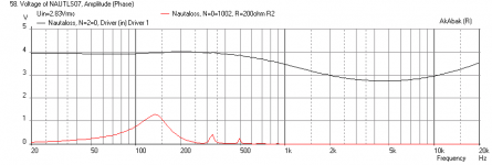
I have confirmed that Akabak does indeed account for driver-to-driver acousto-electrical interactions. In a multidriver cabinet and I simply connected a resistor between the positive terminal of one driver and ground and the negative driver terminal to ground. When you simulate the SPL you see that there is a clear and controllable damping effect of the driver that is connected to the resistor: the response depends on the resistor value and the voltage generated by the driver (driver becomes a dynamic microphone) on the resistor varies with frequency. You can use it as a passive radiator with variable damping in fact. Pretty cool.
Below is the voltage of the driver connected to the amp (black) and the resulting voltage developed across a 200 ohm resistor from the driver that is not connected to the amplifier (red).
Attachments
Last edited:
- Home
- Loudspeakers
- Multi-Way
- Suitable midrange cone, for bandpass mid in Unity horn.