The closer you get the mids to the compression driver, the smaller the cross sectional area is that you tap into. You can run into problems getting the mids to "turn off" when you operate the mid into a small cross sectional area. You will get much higher horn gain at frequencies where the circumference is longer than one wavelength. So let's say you tap into the horn where the area is only 20cm^2. The circumference of 20cm^2 is 15.85cm. This is equal to one wavelength at 2161Hz. Therefore, you will get very high horn gain at frequencies of 2161Hz or lower. Gain will increase as frequency goes down because the wave is acoustically large in relation to the physical horn area. If you wanted to crossover at 1200Hz, this would make "turning off" the mid more difficult.
The above has to do with how I go about selecting the coverage angles of a horn design. You have to balance coverage with what is realistic to build. I would love to build a 60 X 40 Synergy, but with small drivers you start to run into some construction problems. Many of which I am uncomfortable with the required compromises. Just because I feel like I have a good understanding how Synergy horns work, doesn't mean they are any easier for me to build them. I struggle just like everyone else on this forum.
Written in a very understandable manner - Thanks John!
/Thomas
good info, thanks (I'm aiming at 2khz xo)
well, I'm just fooling around as usual
That's going to be near impossible. The distance from the acoustical center of the compression driver to the mid ports would have to be 4.28cm or less.
John!
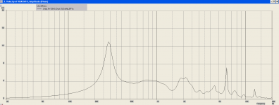
Regarding your Visaton script, couldn't you get away with making the ports smaller then 2.2cm? At 30V input the port velocity only hits 13m/s @ 285Hz.
Maybe I can answer this myself... I reduced the ports to 1.8cm and this resulted in a middle gain loss of 1.5dB, so I'm guessing that would be the reason.
/Thomas
Attachments
John!
Regarding your Visaton script, couldn't you get away with making the ports smaller then 2.2cm? At 30V input the port velocity only hits 13m/s @ 285Hz.
Maybe I can answer this myself... I reduced the ports to 1.8cm and this resulted in a middle gain loss of 1.5dB, so I'm guessing that would be the reason.
/Thomas
Every choice has a cause and effect. Also note that while I choose to simplify the script by using round ports, in real life I use slotted ports. I make the ports' width and length follow the Golden Ratio. So in case of that Visaton M10 script, the ports are approximately 1.55cm X 2.5cm and not really 2.2cm diameter
Every choice has a cause and effect. Also note that while I choose to simplify the script by using round ports, in real life I use slotted ports. I make the ports' width and length follow the Golden Ratio. So in case of that Visaton M10 script, the ports are approximately 1.55cm X 2.5cm and not really 2.2cm diameter
Thanks again, John... That ratio will surely come in handy!
/Thomas
Every choice has a cause and effect. Also note that while I choose to simplify the script by using round ports, in real life I use slotted ports. I make the ports' width and length follow the Golden Ratio. So in case of that Visaton M10 script, the ports are approximately 1.55cm X 2.5cm and not really 2.2cm diameter
Thanks again, John... That ratio will surely come in handy!
/Thomas
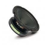
B&C 5FCX44 5" Professional Coaxial Speaker 70° x 70° 8 Ohm 294-5760
New B&C, not terribly expensive.
My thoughts would be to rip off that windscreen,
plug it with a simple wooden cone, and attempt
something of a paraline...
New B&C, not terribly expensive.
My thoughts would be to rip off that windscreen,
plug it with a simple wooden cone, and attempt
something of a paraline...
Thomas you, Hrmmf
Aha!
Well, I actually prefer closed back, cloth surround, paper mids!
Is base my preferences on something JLH wrote about "ideal" midrange characteristics somewhere along this very active and ongoing Synergy thread.
Also, there must be a specific reason to why Danley prefers these types of mids his designs.
/Thomas
I will have to consider a 2" CD
rolled off top is ok for bass guitar
but the higher price is not
though the bigger CD might have other advantages
just now noticed a 1.4" BMS 4554 at 110EUR (and cheap shipping)
funny 1.4" CD, because the cone is the same used in 1" drivers (1.75"/44mm)
recommended 1khz xo point
rolled off top is ok for bass guitar
but the higher price is not
though the bigger CD might have other advantages
just now noticed a 1.4" BMS 4554 at 110EUR (and cheap shipping)
funny 1.4" CD, because the cone is the same used in 1" drivers (1.75"/44mm)
recommended 1khz xo point
Every choice has a cause and effect. Also note that while I choose to simplify the script by using round ports, in real life I use slotted ports. I make the ports' width and length follow the Golden Ratio. So in case of that Visaton M10 script, the ports are approximately 1.55cm X 2.5cm and not really 2.2cm diameter
John, are kepping the width (1.55cm) as i fixed value, solving for x as the length variable:
1.55/x = 0.62 (ratio) -> x = 2.5 ?
Found it!
Golden Ratio
- Still, how do you decide on the width, by hunch ?
/Thomas
with the golden ratio ? ... estimating works fine
with the golden ratio ? ... estimating works fine
- Yes, the Golden ratio!
I mean you have to decide on an initial value, in this case I guess it's the width (1.55cm)
solving: x/1.55 = 1.618 -> x = 2.5
/Thomas
the important thing is that the hole is accurate area
and I suppose all should be equal size
if you also happen to believe in the blessings of golden ratio, that is good enough if estimated
golden ratio is known and proven to please the eye, and give balance in what you see
but I don't know if any other effects have ever been proven
but if designing asymmetric horn, I could still be tempted to use golden ratio between height and width
and should fit the golden ratio rule all the way from mid's pass holes to horn mouth exit
horn length might be a different matter, and depends on horn type
- Still, how do you decide on the width, by hunch ?
/Thomas
I use the Goal Seek function in Excel to find it for me. I have a cell that has the formula something like =A*B. Then I have a cell with formula =A*0.618. The third cell does not have a formula, just an arbitrary number. I then go to the DATA tab in Excel. I highlight the cell with the formula of =A*B. I then click the WHAT IF ANALYSIS. I have Excel solve for the area I want by altering the other two cells.
the important thing is that the hole is accurate area
and I suppose all should be equal size
if you also happen to believe in the blessings of golden ratio, that is good enough if estimated
golden ratio is known and proven to please the eye, and give balance in what you see
but I don't know if any other effects have ever been proven
but if designing asymmetric horn, I could still be tempted to use golden ratio between height and width
and should fit the golden ratio rule all the way from mid's pass holes to horn mouth exit
horn length might be a different matter, and depends on horn type
Correct, getting close is good enough. The Golden Ratio helps prevent standing waves and reduces constructive reflections. Bruce Edgar has been a long time supporter of using a 1:1.6 mouth ratio. I tend to agree with him. I use a several naturally occurring numbers when I design horns. My results have always been better following this. I use the Fibonacci sequence, Prime numbers, Pi, and of course Phi. A lot of times when I'm doing calculations these numbers naturally will pop up. To me this is form telling how it wants to function. Not to say that I depend on these numbers as some kind of voodoo magic design tool. I still approach everything with a scientific mind, but don't get surprised when I see these numbers show up in my calculations.
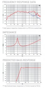
Fane 6" midrange
The design challenges you run into with larger cone mids is it requires much larger port holes to reduce the air velocities. This in turn pushes the crossover point lower, which then forces you to use a larger compression driver, which results in a larger throat area and cross sectional mid tap in point.....etc. And it goes on and on.
The practical cutoff for mid size is about 5.25". You might be about to get away with a 6" if you use a 1.4" or 2" compression driver that can work down to about 600Hz - 700Hz. I had a design for using a pair of Eminence Beta-6A mids with Faital HF146 compression drivers. I never took it anywhere because dropping $500 just on the compression drivers is too much for my blood.
- Home
- Loudspeakers
- Multi-Way
- Suitable midrange cone, for bandpass mid in Unity horn.