Me. ribbons ???? I'm going to use BMS4550s in these horns and hide them in the front corners. I agree aesthetics is an issue but the sound is the primary concern.
The BMS 4550 is hard to beat. It just works so well in a range of crossover points in a Unity/Synergy horn. They are not too expensive either. BTW, the acoustical path length of the 4550 is 6.7cm. When you model in Akabak or Horn Response, take that length into consideration.
An externally hosted image should be here but it was not working when we last tested it.

I'm about to embark on building a new set of Unities. Based on research that I've been doing over the past few weeks, I was thinking about doing a 'hybrid' horn, where one axis of the horn is conical, and the other axis is LeCleach.
My motivation for doing this was that I found that narrowing the first few inches of the horn raised the output of the compression driver in the octave between 1000hz and 2000hz.
And raising the output in that octave will make it easier to 'pass the baton' to the mids in a Unity.
BUT....
Here's the problem:
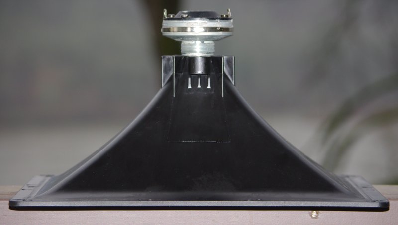
The more I study the problem, I notice that my so called 'invention' looks a heck of a lot like the constant directivity horns that Keele invented forty years ago. And those horns seem to have fallen out of favor. (If you look at the electrovoice horn in the pic above, you can see that in the horizontal axis it's a conical horn; in the vertical axis it's an exponential. So my hybrid "Le Cleach - conical" would look nearly identical.)
So...
I have a couple options here:
1) Go with my 'hybrid' horns, which look suspiciously similar to the Electrovoice horns invented by DB Keele forty years ago
OR

An externally hosted image should be here but it was not working when we last tested it.
2) Go with a QSC waveguide. The QSC waveguide basically uses an oblate spheroidal curve, a la Geddes, but it has a rectangular mouth. My sims and the measurements published online indicate that the QSC won't have as much output between 1000 and 2000hz as the Electro Voice. But it occurred to me that instead of bumping up the output of the compression driver, perhaps I could simply bump up the output of the mids. For instance, if I have a 10db dip at the xover point, I could just raise the output of the mids by ten dB at the xover point. It seems to me that heavy equalization of the midranges should be a lot less obnoxious than 'pushing' the compression driver at the xover point.
I have a MiniDSP so I should be able to achieve response shapes which would be impractical/too complex with a passive xover.
What do you think? Old school constant directivity horn, or new school QSC waveguide?
Last edited:
But it occurred to me that instead of bumping up the output of the compression driver, perhaps I could simply bump up the output of the mids.
The output of the mids have never been a problem for me. Its always been the falling response of the compression driver on the conical horn out at 16KHz to 20KHz. I don't understand how boosting the mids helps this.
The output of the mids have never been a problem for me. Its always been the falling response of the compression driver on the conical horn out at 16KHz to 20KHz. I don't understand how boosting the mids helps this.
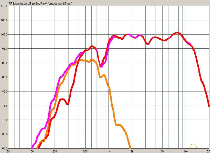
Here's a measurement I did of a pair of 3" drivers on one of my Unity projects. (The 3" drivers are the orange line.)
See how the -6dB point of the mids is 900hz?
My thought is that I could use EQ to raise the output at 1100hz; basically apply a LOT of boost, like ten dB. And that would get the xover point up from 900hz to 1200hz.
300hz doesn't sound like a lot, but with a 1" compression driver it should give it some 'breathing room.'
As for playing above 16khz, I've pretty much given up on that with my Dayton D250Ps. My BMS 4540s and my Celestion CDX1-1425s can do it, but not the Dayton. Diaphragm is just too big and heavy.
Thank you John! I really appreciate your help.
What will be the consequence of this geometry flip (going tall-to-narrow)? Flipping the Beyma won’t change the limited (vertical) dispersion characteristics of the driver.
It seems that the BMS 4550 is the prefered choice, as it "behaves" very well in the Synergy configuration due to its physical properties. What if I wanted to implement the Beyma CD10ND, because I favour it to the BMS? (Rumours say that the CD10ND its a fantastic compresion driver)
What about the half wave cancellation notch - How should one balance this if, hypothetically, a 1.5kHz cross over is the goal?
I’ll probably have some more questions for you as you (hopefully) guide me down the right Synergy path – if it’s not too much trouble.
Scandinavia must have Synergy too (well I do)
/Thomas
This really sadness me, since I already have the Beyma in my possession, and it’s just such a fantastic sounding tweet!You do realize that a 60 X 30 horn on the TPL-150 flips its geometry at around a distance of 16.5cm? (You were positioning the TPL-150’s throat in the vertical plane?) What I mean is it goes from being tall and narrow at the throat to being wide and short at the mouth. You might be better off turning the TPL-150 on its side so you don't get this geometry flip.
What will be the consequence of this geometry flip (going tall-to-narrow)? Flipping the Beyma won’t change the limited (vertical) dispersion characteristics of the driver.
It seems that the BMS 4550 is the prefered choice, as it "behaves" very well in the Synergy configuration due to its physical properties. What if I wanted to implement the Beyma CD10ND, because I favour it to the BMS? (Rumours say that the CD10ND its a fantastic compresion driver)
You’re right. Thank you for pointing that out for me. And, if I move the entry holes even further down the horn, the area of tap in will be too large in relation to the desired cross over, right?The other issue is the local area of expansion where you purpose your midrange tap in point has a flare rate of only 527Hz. This means your mids will only be covering from about 520Hz to 1100Hz. That’s basically an octave. Kind of seems like a waste.
What about the half wave cancellation notch - How should one balance this if, hypothetically, a 1.5kHz cross over is the goal?
I’ll probably have some more questions for you as you (hopefully) guide me down the right Synergy path – if it’s not too much trouble.
Scandinavia must have Synergy too (well I do)
/Thomas
Here's a measurement I did of a pair of 3" drivers on one of my Unity projects. (The 3" drivers are the orange line.)
See how the -6dB point of the mids is 900hz?
If you can't get a 3" mid to go higher than 900hz on a Synergy horn it's time to find a new midrange IMO.
If you can't get a 3" mid to go higher than 900hz on a Synergy horn it's time to find a new midrange IMO.
I'm all ears. If someone can name a midrange that offers these features, I'll buy it:
1) the correct t/s parameters to play to 1500hz on a Synergy horn
2) low distortion
3) doesn't sound 'grungey'


For instance, the 2" buyout mids from parts express play to 1500hz, and with a proper phase plug, the rolloff is well behaved. (Note how the rolloff in the first measurement is better behaved than with 3" or 5" drivers.)
But they sound 'grungey' to my ears; I believe the underhung motor and shorting rings of the Peerless 3" is making it sound "cleaner"
So it's a bit of a catch-22. There are drivers that sound clean with underhung motors and shorting rings, but those features add weight to the moving mass and that makes the T/S parameters wrong for a 1500hz crossover. And there are drivers with the right T/S parameters, but they often sound 'grungey' to me.
Among this mess of drivers, we have some outliers. The Misco and Pyle woofers are lo-tech, but the cones move so little it seems to keep the 'grunginess' to a minimum. The TB W2-852SH is underhung, but they're so small they manage to keep the T/S parameters in the right range. To me, the Faital 3" sounds a lot like the TB 2" drivers also.
And then there are drivers like the Peerless 2" and 3", that have both an underhung motor *and* shorting rings, and it seems like it *might* be possible to get them up to 1500hz with a bit of careful engineering.
You do realize that a 60 X 30 horn on the TPL-150 flips its geometry at around a distance of 16.5cm? (You were positioning the TPL-150’s throat in the vertical plane?) What I mean is it goes from being tall and narrow at the throat to being wide and short at the mouth. You might be better off turning the TPL-150 on its side so you don't get this geometry flip.
The other issue is the local area of expansion where you purpose your midrange tap in point has a flare rate of only 527Hz. This means your mids will only be covering from about 520Hz to 1100Hz. That’s basically an octave. Kind of seems like a waste.
I've used ribbons on a couple of my Unity horns.
The first ribbon exploded; before building anything, I'd look and see what the cost of replacement ribbons are, and how much hassle they are to replace.
USSpeaker sells the Beyma for $960 a pair, so replacement ribbons might be spendy.
You have four midranges 'pushing' against the ribbon diaphragm and that might create distortion, or even blow the ribbon up.
I personally won't be trying ribbons on a Unity horn again, simply because it didn't sound too good. But my ribbons were cheap (about $250 a pair) so you may have better luck.
All the horns that I’ve listened (a couple of them were my own designs) to that go through a geometry flip just sound a bit weird. Something just sounds off about them. I really can’t explain any better. I agree the TPL-150 is an excellent driver. It just doesn’t lend itself to being implemented in a Unity/Synergy design.
You can implement any compression driver you like. I don’t know much about the CD10ND, but have listened to the CP380/M and CP385Nd in several designs. Both were very good sounding in their designs. I would think they would perform fine in a Unity/Synergy design, but I can’t be certain.
Correct, moving the entry holes down the horn will increase the cross sectional area they tap into too much and you will not be able to reach 1KHz. At the same time the further you move down the horn, the lower the local area flare goes. You have to balance the ½ wave cancellation notch distance with the area of the horn where you tap in. It just so happens this is much easier to do with a compression driver.
The ideal balance is when the circumference of the area the mids tap into is equal to one wave length of the highest frequency, and the distance between the acoustical center of compression driver and mids is half a wave length of the highest frequency. In your case of 1.5KHz this would mean that you want to tap the mids into the horn with an area of 41.53cm^2 that is 11.42cm from the acoustical center of the compression driver.
You can implement any compression driver you like. I don’t know much about the CD10ND, but have listened to the CP380/M and CP385Nd in several designs. Both were very good sounding in their designs. I would think they would perform fine in a Unity/Synergy design, but I can’t be certain.
You’re right. Thank you for pointing that out for me. And, if I move the entry holes even further down the horn, the area of tap in will be too large in relation to the desired cross over, right?
What about the half wave cancellation notch - How should one balance this if, hypothetically, a 1.5kHz cross over is the goal?
Correct, moving the entry holes down the horn will increase the cross sectional area they tap into too much and you will not be able to reach 1KHz. At the same time the further you move down the horn, the lower the local area flare goes. You have to balance the ½ wave cancellation notch distance with the area of the horn where you tap in. It just so happens this is much easier to do with a compression driver.
The ideal balance is when the circumference of the area the mids tap into is equal to one wave length of the highest frequency, and the distance between the acoustical center of compression driver and mids is half a wave length of the highest frequency. In your case of 1.5KHz this would mean that you want to tap the mids into the horn with an area of 41.53cm^2 that is 11.42cm from the acoustical center of the compression driver.
If you can't get a 3" mid to go higher than 900hz on a Synergy horn it's time to find a new midrange IMO.
This is not the case. In every case I've found the tap in point to be the reason why the mids drop off too early. Even piece of crap Curtis Mathes mids can work well into the 2KHz to 3KHz range.
I'll go over this one last time. To reach your desired high frequency output of the mids the following must be true:
1.) The circumference of the cross sectional area must be equal to or less than 1 wave length of the highest frequency.
2.) The distance between the acoustical center of the compression driver and the tap point must be one half a wave length or less.
In most cases people are getting the mids close (satisfying number 2), but fail to ensure the area is correct.
Everyone needs to re-read the Synergy horn patent again.
http://www.goodsoundclub.com/PDF/Synergy_Patent.pdf
Last edited:
Hi JLH:
Could you also clariy flare rate for me; I don't quite get the details and I find the explanation in the synergy patent difficult. I, perhaps incorrectly, think of flare rate with the rate of change of cross sectional area vs distance from the apexm a simple calculation for a conical horn. This is a distance squared divided by a distance so the result is a distance. When someone talks about flare rate in terms of a frequency, is he equating that distance to a wavelength? Or is to the cutoff frequency an exponential horn would have? Or something else?
thanks for your help
http://www.diyaudio.com/forums/mult...e-bandpass-mid-unity-horn-15.html#post2404697
"On page 4, it explains why conical horns have a variable flare rate. At the throat the flare rate is high, as you move to the mouth the flare rate lowers. The local expansion rate determines the flare rate. To find the local flare rate you can use Horn Response. Input the values for your conical horn and then change the horn type from Conical to Exponential and Horn Response will calculate the flare rate for you. What the compression driver "sees" is the throat and the distance required to double in area." (JLH)
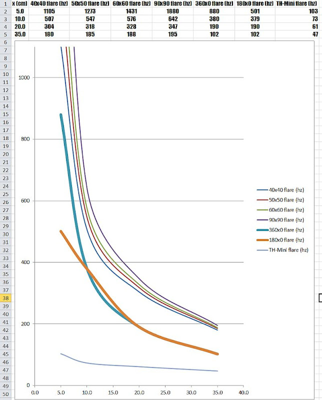
Here's a graph which compares the 'local flare rate' of various horns, at various distances along the horn's pathlength.
You can calculate this by hand, or calculate it via hornresp
If I'm not mistaken, the formula for doing it by hand is in one of the PDFs at quarter-wave.com;
I did it with hornresp, using the instructions provided by John in this thread a couple years back
The graph is from page 73 of this thread. If you have any questions on what the various curves are, please let me know.
Some observations from yours truly:
1) Horns with narrower coverage allow you to put the mids further away; this is one of the reasons I find narrow coverage horns compelling for Unity horns, despite the fact that their coverage (arguably) isn't ideal. (See how the 90x90 requires that the mids are closer to the compression driver than the 40x40?)
2) When you're calculating the 'local flare rate', keep in mind that a horn can be segmented so that it's a horn on top of a horn on top of horn on top of a horn. In other words, the flare rate at the horn mouth is a certain value, but the flare rate at a point along the horn is a completely different (and smaller) value. But you can model that easily, just simulate the horn segment in hornresp, instead of the entire horn.
This gets particularly maddening if you try to factor the pathlength between the diaphragm and the exit of the compression driver
"On page 4, it explains why conical horns have a variable flare rate. At the throat the flare rate is high, as you move to the mouth the flare rate lowers. The local expansion rate determines the flare rate. To find the local flare rate you can use Horn Response. Input the values for your conical horn and then change the horn type from Conical to Exponential and Horn Response will calculate the flare rate for you. What the compression driver "sees" is the throat and the distance required to double in area." (JLH)
Here's a graph which compares the 'local flare rate' of various horns, at various distances along the horn's pathlength.
You can calculate this by hand, or calculate it via hornresp
If I'm not mistaken, the formula for doing it by hand is in one of the PDFs at quarter-wave.com;
I did it with hornresp, using the instructions provided by John in this thread a couple years back
The graph is from page 73 of this thread. If you have any questions on what the various curves are, please let me know.
Some observations from yours truly:
1) Horns with narrower coverage allow you to put the mids further away; this is one of the reasons I find narrow coverage horns compelling for Unity horns, despite the fact that their coverage (arguably) isn't ideal. (See how the 90x90 requires that the mids are closer to the compression driver than the 40x40?)
2) When you're calculating the 'local flare rate', keep in mind that a horn can be segmented so that it's a horn on top of a horn on top of horn on top of a horn. In other words, the flare rate at the horn mouth is a certain value, but the flare rate at a point along the horn is a completely different (and smaller) value. But you can model that easily, just simulate the horn segment in hornresp, instead of the entire horn.
This gets particularly maddening if you try to factor the pathlength between the diaphragm and the exit of the compression driver
Last edited:
Hi JLH:
Could you also clariy flare rate for me; I don't quite get the details and I find the explanation in the synergy patent difficult. I, perhaps incorrectly, think of flare rate with the rate of change of cross sectional area vs distance from the apexm a simple calculation for a conical horn. This is a distance squared divided by a distance so the result is a distance. When someone talks about flare rate in terms of a frequency, is he equating that distance to a wavelength? Or is to the cutoff frequency an exponential horn would have? Or something else?
thanks for your help
The easiest way is to use Horn Response to perform the flare rate calculation. In the Synergy Horn patent is says that the local area flare rate is taken as the distance it takes for the point to double in area. This means if you tap into the horn where the area is 42cm^2, you want to know the length at which the area has become 84cm^2.
Example: Go ahead and input the data for your offset horn in Horn Response. Double click on the conical section where the mid taps in. Click calculate, this calculates the angle for the section. Next click the bubble to calculate length of that section and input 84cm^2 for the mouth section. Horn Response will calculate the length that section takes to double in area (42cm^2 -> 84cm^2). Click OK and save the calculation. Now click on the data field that reads CON and hit the "E" key on your keyboard to change it to an exponential contour. To the far right it will tell you what the flare rate is. This number is how low the mid will play. It will NOT play any lower than this. You can't get a driver to deliver any significant output below the flare rate it is loaded to.
In addition, you must do the same for your compression driver. For a 1” compression driver the starting area is 5.07cm^2. Find the flare rate that the compression driver sees, so you know how low it will be able to play. To avoid coloration and honk, you want the flare rate it sees to be lower than the crossover point. (e.g. If the compression driver’s local area flare rate is 1000Hz, then you want to highpass it at something like 1100Hz or 1200Hz.) As you would expect, more narrow horns will allow a lower crossover for the compression driver. It doesn’t matter if we are talking compression drivers, midranges, woofers, etc they all follow the rules of horn loading.
Here's a graph which compares the 'local flare rate' of various horns, at various distances along the horn's pathlength.
If you want to make things even easier for yourself you should adjust the graph to plot the flare rate along with a line that shows the 1/2 wave length cancellation frequency. Where the two lines intersect is an ideal crossover point.
Awesome help. Let me see if I got it right.
I double clicked in the S2 box below the S1 box on the input parameters screen
There S2 was 127.5 so when I calculated the length I ended up with 255 for S3 and a length of 3.08 cm. When I converted the CON to EXP I got an F23 of 615.85.
This was for a 90x60 horn with horiz pattern control down to 256 hz, per B.Waslo's xls
Does that sound right. If so, I am a happy camper!
Awesome help. Let me see if I got it right.
I double clicked in the S2 box below the S1 box on the input parameters screen
There S2 was 127.5 so when I calculated the length I ended up with 255 for S3 and a length of 3.08 cm. When I converted the CON to EXP I got an F23 of 615.85.
This was for a 90x60 horn with horiz pattern control down to 256 hz, per B.Waslo's xls
Does that sound right. If so, I am a happy camper!
Those are the same numbers I get.
I ran a 60x60 horn model I had with an S1 of 3.2 and got a CD flare rate of 2790 hz
I did the math and I see 1" dia circle is indeed 5 sq.cm. Why then does Bill's spreadsheet start with S1 of half that?
but what about the 6.7 cm acoustic path length (for the BMS4550) inside the driver and phase plug? Will the flare rate of the phase plug determine the low end response limit?
I did the math and I see 1" dia circle is indeed 5 sq.cm. Why then does Bill's spreadsheet start with S1 of half that?
but what about the 6.7 cm acoustic path length (for the BMS4550) inside the driver and phase plug? Will the flare rate of the phase plug determine the low end response limit?
If you want to make things even easier for yourself you should adjust the graph to plot the flare rate along with a line that shows the 1/2 wave length cancellation frequency. Where the two lines intersect is an ideal crossover point.
OK!
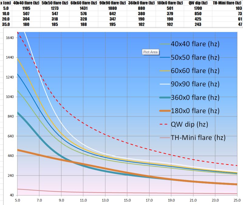
The graph above shows the local flare rate of various horn geometries, and Paralines too.
Based on John's instructions here: http://www.diyaudio.com/forums/mult...e-bandpass-mid-unity-horn-81.html#post3468056
I believe that I would go through the following process if I was designing a 50x50 Synergy horn:
1) The first step in figuring out the location of the tap is to insure that the tap's location is *beyond* the transition from the high frequency horn, to the midrange horn. (IE, we're making a 'horn on a horn', and the two horns need to 'get out of each others way') If I opt to use an xover point of 1000hz and a 50x50 horn, then the end of the high frequency horn is 6.75cm from the throat.
2) Now that I know where my high frequency horn ends, I need to see the impact of the quarter wave reflection. Looking at the same graph, I see that the quarter wave reflection will happen at 1440hz. That's actually a little bit too high, since I want to use an xover point of 1000hz. We're going to get an overlap between 1440hz and 1000hz. To get things to line up better, I push the midrange taps out to 8.75cm. That moves the quarter wave dip down by 500hz, and it also gets the midrange further 'out of the way' of the compression driver. (Remember, the compression driver basically 'can't see' the midranges if you do this right.)
Naturally, you'll notice that these two numbers are a fraction of an inch apart.
- Home
- Loudspeakers
- Multi-Way
- Suitable midrange cone, for bandpass mid in Unity horn.