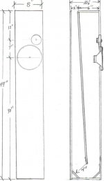
after quite a few different design ideas (firstly a ported bookshelf w/ help from madisound) i think i have finally arrived at a design i want to build.
i wanted to use a single sheet of 3/4" mdf so that limited the size and shape, but i think (hope) i arrived at pretty good compromise
also, how much tweeking must be done to use the crossovers originally designed for the ported box in the new set-up?
please let me know what you think.
drivers......
pl18wo-04
d27tg35
Attachments
i have tried to model this using mjk's worksheets, but i dont know how to save the graphs to post them,
and i am not quite convinced i modeled them correctly anyway.
so if anyone could model it or tell me how to post them it'd be appreciated.
and i am working on drawing up the crossover so hopefully someone can take a look and see if it is ok.
thanks
and i am not quite convinced i modeled them correctly anyway.
so if anyone could model it or tell me how to post them it'd be appreciated.
and i am working on drawing up the crossover so hopefully someone can take a look and see if it is ok.
thanks
I would expect the original xo frequency to be high enough that the cabinet design would not affect it. Most of the effect of the cabinet design would be in the low bass, although there might be a secondary effect depending on whether the original xo was designed with a baffle step, and if you've changed the cabinet width or tweeter position on the faceplate.
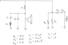
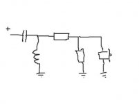
the origional crossover is below, i think bsc was taken into consideration, but i dont know for sure. if it was designed in, is it appropriate for an 8" baffle?
also, could someone tell me the approx crossover point and slopes.
i am working on the mjk sims so hopefully i can get them up shortly.
thanks
also, could someone tell me the approx crossover point and slopes.
i am working on the mjk sims so hopefully i can get them up shortly.
thanks
Attachments
elfranche said:I've used the D27 for some years. very nice..
I used to like it as well until I started running into so many bad ones that I don't dare buy D27's anymore, and this applies to all of them (15's, 35's and 45's). The risk of having problems is simply too high. By "problems" I mean units that measure way outside their published specs and don't even come close to matching with one another. It's not a question of tolerances, they're just plain bad. I know Vifa supposedly fixed problems with the D27 but I've had problems with the "fixed" ones as well so I have my doubts. I'm very close to thinking that the D27 line was poorly designed, plain and simple. This being said I have no complaints about other Vifa tweeter models, I especially appreciate the D25 and D26 but unfortunately these are hard to come by these days. But on the bright side of things, is there are better quality tweeters that sell for less (at least in North America) available to DIY'ers now, such as Hi-Vi units.
As for the PL18, in my personal experience it's an excellent driver. Pricey for a Vifa but it's in a different league than other Vifas and considering its quality it's a good value. Chinese made drivers of similar quality don't sell for much less, when they aren't more expensive. This is just my personal opinion, based on my own listening. The PL line is quite new and I haven't seen any thorough reviews of those drivers yet. I sure would like to.
I beleive the first one is correct and is a second order 12db slope with an L-pad on the tweeter and a Zobel circuit on the woofer.
Is this correct?
Hi nebelk,
I think your crossover is incorrectly designed as the L2 coil shorts the filter to ground at low frequencies and the 20-Ohm resistor is also misplaced.
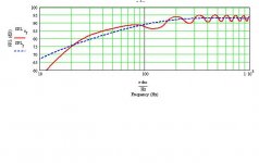
Your Zobel network doesn’t deal with the bump issue close to the crossover frequency.
See label B at ncgraph.gif.
B
Attachments
Hi nebelk,
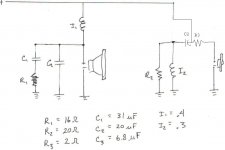
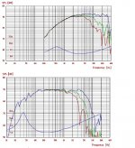
In your post # 5 you’ve shown us a crossover, referring the tweeter section, a schematic that looks kind of weird.
Take a look at the new picture and the impedance plot labelled ‘A’ that corresponds to your submitted crossover where you can see that the impedance of the speaker drops under 1 Ohms at about 550 Hz and further down for lower frequencies.
Maybe your amplifier can withstand this low ohmic load, or this crossover is just drawn incorrectly and in the reality is ok.
But is this really, the crossover in use? Don’t worry about the component values for the moment, they are in the ballpark, but please check and compare your schematic and the implemented filter again!
When I rearranged your filter to a more probable one, as in circuit label ‘B’, I found your Zobel network consisting of C1 and R1 not doing the proper job, so I calculated new values.
Look at the result in the plot labelled ‘C’. The speaker peak impedance has lowered from about 17 Ohms to about 9 Ohms and the ‘bump’ in earlier submitted circuit ‘B’ and the voltage plot for label ‘B’ is gone.
It’s not my intension to confuse you more, but maybe I do, as my native language is not English.
Maybe someone else can help you further; if I failed to explain what I think is wrong with your crossover circuit/drawing?
B
In your post # 5 you’ve shown us a crossover, referring the tweeter section, a schematic that looks kind of weird.
Take a look at the new picture and the impedance plot labelled ‘A’ that corresponds to your submitted crossover where you can see that the impedance of the speaker drops under 1 Ohms at about 550 Hz and further down for lower frequencies.
Maybe your amplifier can withstand this low ohmic load, or this crossover is just drawn incorrectly and in the reality is ok.
But is this really, the crossover in use? Don’t worry about the component values for the moment, they are in the ballpark, but please check and compare your schematic and the implemented filter again!
When I rearranged your filter to a more probable one, as in circuit label ‘B’, I found your Zobel network consisting of C1 and R1 not doing the proper job, so I calculated new values.
Look at the result in the plot labelled ‘C’. The speaker peak impedance has lowered from about 17 Ohms to about 9 Ohms and the ‘bump’ in earlier submitted circuit ‘B’ and the voltage plot for label ‘B’ is gone.
I am somewhat confused,
It’s not my intension to confuse you more, but maybe I do, as my native language is not English.
Maybe someone else can help you further; if I failed to explain what I think is wrong with your crossover circuit/drawing?
B
Attachments
Thank you for your continued help, it is not your English that is the problem, but my lack of knowledge regarding crossover design.
The crossover in post #5 was designed by someone (not me) for these speakers in a simple prted box, however, in moving last spring I lost the actually drawings, therefore I tried to draw them from memory, which I apparently did incorectly.
I had previosly ordered the parts so that is where I got the values from, but changing them is not a problem, as the crossovers were never assembled.
In your opinion, would it be best to build and use C that you have posted?
thank you again
-k
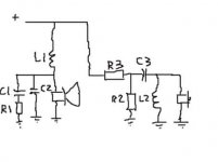
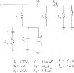
And R2 and R3 can also be put after the filter (C3 and L2)..*
R2 and R3 are attenuation...
C3 and L2 are a 12db/oct. 2nd order high-pass filter.
L1 and C2 are a 12db/oct. 2nd order low-pass filter.
C1 and R1 are perfectly described by Bjorno...
Crossover freq is on the lower side for a 2-way, think it's 'round 2.5 to 3 Khz...
*like this:
R2 and R3 are attenuation...
C3 and L2 are a 12db/oct. 2nd order high-pass filter.
L1 and C2 are a 12db/oct. 2nd order low-pass filter.
C1 and R1 are perfectly described by Bjorno...
Crossover freq is on the lower side for a 2-way, think it's 'round 2.5 to 3 Khz...
*like this:
Attachments
Hi Nebelk,
You latest filter crossoverc.jpg looks ok for me.
Thank you v-bro for assisting and showing the other option using L-pad resistors!
I will model this filter variant and post it tomorrow, my time.
I think you should start using the label ‘B’ circuit before using ‘C’ because the designer has probably already tested it ok when listening to the speakers.
Maybe the bump doesn’t exist at all and is in my case only caused due to the distance between the drivers.
My assumption is zero distance when I modelled your filter and might be practically wrong in the reality when coincident drivers are not the option for your speakers.
In this Zobel network, the only component that looks too high in value is the resistor R1, because PL18WO-04’s impedance is almost doubled at the crossover frequency.
A minor and narrow amplitude bump is also very difficult to recognize in that frequency area.
I recommend you to test with other lower values of R1 later and first after listening to the label ‘B’ variant.
By the way, I also think your tweeters height above the floor level is not at normal ear level.
My suggestion is to place the tweeters below the woofers as your speaker with LR2 filter projects the main frequency lobe perpendicular to the baffle.
You will not recognise much difference if the tweeter is placed below the woofer and the ‘Pratts effect’ will even make your central phantom sharper when listening at tweeter/woofer combination at the correct ear level.
B
- Status
- This old topic is closed. If you want to reopen this topic, contact a moderator using the "Report Post" button.
- Home
- Loudspeakers
- Multi-Way
- opinions on vifa pl18 tl