bjorno,
When I was modeling this in mjk's worksheets, moving the driver down did not affect the graphs too dramatically, this being so would you recomend moving both the driver and tweeter down or placing the tweeter below, will anything change beyond aesthetics?
I'll have to google 'Pratts effect'
I am also curious what everyone feels ideal listening height should be
thanks
-k
will anything change beyond aesthetics
The only thing that could happen, is the slight change of baffle edge reflexes within about 700uS or 9.5”, causing a small location change within the c-c distance of the tweeter/woofer and a small change of the MAA (minimum audible angle), the resolution of the phantoms.
For possible tonal colouring change, I think the CMAA (concurrent MAA) will be a JND matter.
Read about Pratts effect here: http://www.idc.ul.ie/icad2005/downloads/f49.pdf
I am also curious what everyone feels ideal listening height should be
First, you don’t need to move the woofer, only the tweeter as I can see.
Place yourself at your favourite, seat sofa or chair and measure your ear height and use it.
B
I would recommend making the listening height on the low side. Lifting the speaker with an extra tile or plymth can be easily done to get the right height by listening what sounds best...
The latest posted schematic is indeed correct.
The graphs show quite low fs for your tweeter, the value of C3 (6.8uF) is fine, but you might want to experiment on a slightly lower value if mids sound coarse...
The graphs also show slightly higher sensitivity on the tweeter, but
the attenuation looks allright, don't mix the values on those resistors!
The series-parallel design saves resistance on the signal path, many designers would only put a single 3 to 8 ohm resistor in series..
So It looks allright to begin with.
Tip: put your box on three feet, it won't unsettle!")
The latest posted schematic is indeed correct.
The graphs show quite low fs for your tweeter, the value of C3 (6.8uF) is fine, but you might want to experiment on a slightly lower value if mids sound coarse...
The graphs also show slightly higher sensitivity on the tweeter, but
the attenuation looks allright, don't mix the values on those resistors!
The series-parallel design saves resistance on the signal path, many designers would only put a single 3 to 8 ohm resistor in series..
So It looks allright to begin with.
Tip: put your box on three feet, it won't unsettle!
Willitwork said:
I used to like it as well until I started running into so many bad ones that I don't dare buy D27's anymore, and this applies to all of them (15's, 35's and 45's). The risk of having problems is simply too high. By "problems" I mean units that measure way outside their published specs and don't even come close to matching with one another. It's not a question of tolerances, they're just plain bad. I know Vifa supposedly fixed problems with the D27 but I've had problems with the "fixed" ones as well so I have my doubts. I'm very close to thinking that the D27 line was poorly designed, plain and simple. This being said I have no complaints about other Vifa tweeter models, I especially appreciate the D25 and D26 but unfortunately these are hard to come by these days. But on the bright side of things, is there are better quality tweeters that sell for less (at least in North America) available to DIY'ers now, such as Hi-Vi units.
I have heard that too. I have used the Seas 27TFFC tweeter and it sounds way better to my ears that the price would indicate.
As for the PL18, in my personal experience it's an excellent driver. Pricey for a Vifa but it's in a different league than other Vifas and considering its quality it's a good value. Chinese made drivers of similar quality don't sell for much less, when they aren't more expensive. This is just my personal opinion, based on my own listening. The PL line is quite new and I haven't seen any thorough reviews of those drivers yet. I sure would like to.
I have 4 of them (the 4 ohm ones) and they are quite nice drivers. I'm working on an active crossover TL MTM with them and an XT25 at the moment. I'm using chip amps and the entire crossover and amp system will live inside the speakers. The entire stereo system will consist of a squeezebox and a pair of speakers...Tidy
Sheldon
Nebelk,
I promised to post a new plot for the before mentioned L-pad in front of your tweeter.
It didn’t improve the filter so I will hereby withdraw my promised picture, as it’s worse than the one I have shown earlier.
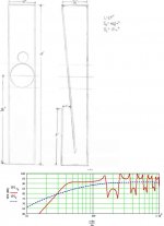
But, I simulated your ‘vifa.jpg’ today, just of curiosity and draw the conclusions that your TL simulation is in my opinion severely misaligned.
There is nearly no cone control at all and the tuning is far to low in my opinion, about 18 Hz.
At 5 W input you will hit x-max for 30 Hz at a low 88dB SPL.
If using a 50 Litre box, So=2.5 and SL=1 and L=80”, input power capability doubles when tuned to 30 Hz/ at 93dB SPL.
B
Edit : L is the total TL line lenght!
I promised to post a new plot for the before mentioned L-pad in front of your tweeter.
It didn’t improve the filter so I will hereby withdraw my promised picture, as it’s worse than the one I have shown earlier.
But, I simulated your ‘vifa.jpg’ today, just of curiosity and draw the conclusions that your TL simulation is in my opinion severely misaligned.
There is nearly no cone control at all and the tuning is far to low in my opinion, about 18 Hz.
At 5 W input you will hit x-max for 30 Hz at a low 88dB SPL.
If using a 50 Litre box, So=2.5 and SL=1 and L=80”, input power capability doubles when tuned to 30 Hz/ at 93dB SPL.
B
Edit : L is the total TL line lenght!
Padding the cabinet on the inside for what I've understood will slow down wavespeed.. and make the line virtually shorter..
Sorry, but that is an old rule of thumb that has been shown to be incorrect. The padding will help damp resonances but it will not slow the speed of sound and lead to a shorter required length.
Vbro,
Nebelk’s TL have a line length about 2.5 m and is tapered.
The quarter wavelength for the driver of fs = 37 Hz is 2.32 m.
A straight 2.32 m non-tapered tube without any ‘padding’ would be sufficient to restrict excessive cone motion at the fs.
Nebelk’s TL which is tapered has a quarter-wave resonance below 25 Hz without any ‘padding’.
By the way, Nebelk’s TL might use a baffle step compensation too of 1.2 mH paralleled with 3 Ohm.
B
What do you think of the intial design MJK?
I really can't comment on the drivers or crossover since I have not looked closely at them or used them in any projects. But the plotted SPL response for the TL, in one of the earlier posts, does not look all that impressive. I would not expect too much bass from this design and would probably recommend a redesign.
thanks for the replies everyone
my initial design was based more on aesthetics than on knowledge of how a TL should be properly designed, so I figured some change would be necessary, perhaps a complete redesign.
bjorno, I will run your design using MJK sims, luckily a winter storm just moved in and any wood cutting has been pushed back indefinitely.
hopefully I can draw up an post a more feasible design later
-k
Hi Nebelk,
The TL length is about right now but:
Please make your drawing more readable and fill in all the question marks.
Your simulation must be backed up with ..all… data used when simulating your speaker, otherwise it’s impossible to help you further.
B
The TL length is about right now but:
Please make your drawing more readable and fill in all the question marks.
Your simulation must be backed up with ..all… data used when simulating your speaker, otherwise it’s impossible to help you further.
B
Attachments
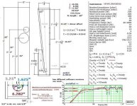
bjorno, sorry for the lack of clarity and information in my last sketch.
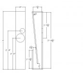
I have redrawn it in autocad so hopefully it is a bit more clear.
I am unsure what exactly the offset should be in MJK's sims, I thought it was the ratio of drvier offset from top of line / line length, but it should be the length from the driver center to the top of the line, correct? I think this may be why my sims are off.
for example, in the attached drawing, driver offset = 21.25" and not 21.25"/L.
In the sim I posted there was no stuffing, I was going to address that later.
as for T/S parameters, I used what is shown on madisound
I am a little uncertain what the total line length of the attached drawing is, do you think you could help me out here as well.....
any other suggestions are greatly appreciated, and thank you for your help and continued interest.
-k
Attachments
Hi to you all,
Have to work so hard these days it's nearly impossible to find the time to be here... , ,, and again...
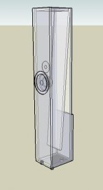
Just want to say you should make sure you attach the stuffing to the enclosure well, wool for instance -a good material for a TL- is heavy and tends to sink to the bottom causing the line to be blocked....
In this type of design it is also very important to get the size of the line under the upper backpanel right (in practice, not calculations). Some designs feature bent panels in corners and rounded panel edges. I would think this is worth the extra effort...
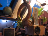
I built TLs like this once:
Have to work so hard these days it's nearly impossible to find the time to be here...
, ,, and again...Just want to say you should make sure you attach the stuffing to the enclosure well, wool for instance -a good material for a TL- is heavy and tends to sink to the bottom causing the line to be blocked....
In this type of design it is also very important to get the size of the line under the upper backpanel right (in practice, not calculations). Some designs feature bent panels in corners and rounded panel edges. I would think this is worth the extra effort...
I built TLs like this once:
Attachments
I am a little uncertain what the total line length of the attached drawing is, do you think you could help me out here as well.....
Actual line length appears to be 61.76".
Jeff
Hi Nebelk,
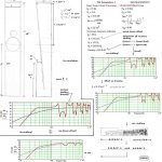
Your TL driver is placed about a 1/3rd down and will suppress or cancel the first overtone (the 3rd harmonic).
The total line length can be calculated as MJK shows or the simple average way I show in my picture, both methods will work.
You have to consider the wall thickness and to cross brace the internals of your speaker, at least 30” (forming three sections?) from the top and down; the pressure build-up can be substantial behind the driver.
Crossbraceing’s will hold the stuffing materials in place.
For a speaker built with MDF I would use minimum 5/8 “of thickness throughout besides the baffle which I would make at least ¼” thicker and also recess the woofer with the tweeter flush mounted on the baffle.
I would not use sheep wool, any synthetic intended for stuffing loudspeakers will do fine and I also use 3/8" to 5/8" thickness of dens wool felt to line (spray glued) the areas around the driver, in your case the first tapered section to the box bottom.(about 46" of the tapered lenght)
A spare compartment, about 2” high at the bottom of the speaker, is very useful to hide the filters and to mount the binding posts at the removable lid is also a good idea
B.
Attachments
thanks for all the help bjorno, having someone who knows what they're doing help me is encouraging
I plan on using 3/4" MDF, with ample crossbracing
a spare compartment at the bottom is a good idea, I think I may implement it
I will post pics as soon as construction begins
-k
I plan on using 3/4" MDF, with ample crossbracing
a spare compartment at the bottom is a good idea, I think I may implement it
I will post pics as soon as construction begins
-k
- Status
- This old topic is closed. If you want to reopen this topic, contact a moderator using the "Report Post" button.
- Home
- Loudspeakers
- Multi-Way
- opinions on vifa pl18 tl